prasanth1216
Newbie level 3
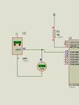
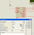
I'm trying to read the temperature from a LM35 sensor and print it on an LCD display using PIC 16F877.. But I'm getting an error message in PROTEUS ISIS as 'Power Supply' (1.52v) is outside specified range(3.5v-30v)..
Pls help me .

Pls help me .