Continue to Site

Welcome to EDAboard.com

Welcome to our site! EDAboard.com is an international Electronics Discussion Forum focused on EDA software, circuits, schematics, books, theory, papers, asic, pld, 8051, DSP, Network, RF, Analog Design, PCB, Service Manuals... and a whole lot more! To participate you need to register. Registration is free. Click here to register now.

problem regarding k700 and 89s51

Status
Not open for further replies.

kamalBMI

Newbie level 6
Newbie level 6
Joined
Jun 5, 2010
Messages
14
Helped
0
Reputation
0
Reaction score
0
Trophy points
1,281
Activity points
1,402
hello guys.... I started posting again... and ya, its about the same thing again... .
my project is in the last stage of completion... I manage to connect my phone sony k700 to PC with the connection as below

phone-->max232---> pc

with this connection I'm able to send AT command to the phone via hyperterminal and I got the desired feedbacks. Other than that, I've also done proteus simulation using the above connection. From the simulation, all is working perfectly...

HERE'S THE PROBLEM... when I construct the hardware and connect all of them , it doesn't seem to be working... right now I'm using the connection as the following...

phone--->max232--->max232(again)---->89s51

Can anybody help me out? I'll supply all the necessary info afterwards... plss.. my duedate is in a week and I don't know what to do...
 

You can connect k700 directly to 89s51. What is the problem? why are you using 2 level converters?
 
If the 2 MAXs are required for your circuit then there may be change in baud rate settings.
Regards,
Jerin.
 
first of all, thanks for your quick replies... I really do appreciate it.... I do... I hope u guys can guide me all the way....

well sir, actually I thought the connection is like this...

phone---->max232--->pc

89s51---->max232--->pc

combining them both

phone--->max232--->max232(again)---->89s51

or am I wrong about this? (!-_-)

---------- Post added at 06:47 ---------- Previous post was at 06:45 ----------

jerin... how to calculate about the baud rate? do explain more sir...
 

Let me ask one question.Is this MAX needed for the phone to be connected to the PC? Can't we connect via USB to the PC?
But in the second case MAX is needed.I have a doubt in the first case.
Regards,
Jerin.
 
thanks for your reply jerin... The original usb cable use usb connection... but I modified it so that it use serial connection.... then I connect it to the comport of the pc and talk to it via hyperterminal... this is the screen shots of the experiment I did earlier....


---------- Post added at 07:07 ---------- Previous post was at 07:03 ----------

*the original data cable use usb connection
 

So if you are connecting via the com port too i think you won't be requiring the MAX there.
Regards,
Jerin.
 
sir, I think I still need the max232... when I modified the data cable what I mean is that I connect the data cable to the max circuit and then only I connected it to the pc... I also run a simple test just now... I connected the hardwares as the following

k700---->max232---->max232(again)---->89s51

then, I burn a program into 89s51 that will transmit ATD0125410400 which tell the phone to dial the given numbers and it did.... However, when I burn the program which work with proteus nothing happen...Supposely the 89s51 should trigger the relay when I send sms to the k700 but it didn't.. My guess is

1. the 89s51 failed to act according to the feedback of the phone
2.the feedback from the phone failed to reach 89s51

Pls... if anybody have any idea or suggestion I'm open and would gladly try them out... I'll also shared the program,drawings and etc if u need them in order to help me out... I believe there's something that I miss out while doing this project... thanx in advance...
 

So you say that a MAX is required to transfer the commands from the phone to the PC. Isn't it? Let me ask you one question.What is your projects name?
Regards,
Jerin.
 
yup... In my opinion it need max to connect to pc... my project is "sms controlled relay".... Sir, any idea to make my circuit functioning? my head is cracking open to find the solutions... huhu...
 

Do one thing. Instead of connecting the controller to the relay do try to blink an LED on the controller side or try to do a simple thing so that we can make out where the error is.Try this method @ the phone level side too.
Regards,
Jerin.
 
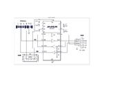
thanks sir for continous replies... you've been great... I'm trying out your suggestion.. (this maybe quit silly)huhu... but where actually to put the LEDs? this is the max circuit use for the phone
[/url
 

i quite dint follow the whole post line.. but just a suggestion if u re using two MAX232s.. y not use two different lines of a single MAX232?
 
jerin... how to calculate about the baud rate? do explain more sir...
Its there in the UART section in the data sheet of the controller you are using.Just refer to that.It is explained nicely there.
but where actually to put the LEDs?
You can place the LEDs in any one of the free pins you have got in the controller. Just SET the led connected pin of the controller when a certain condition is satisfied i.e on desired output.
Regards,
Jerin.
 
You say you connect your fone to PC's COM Port and it works!
Did you check you Microcontroller works with PC MAX (write a simple prog which echos back the same character)

here is the way
Phone> MAX >PC (does your phone requires MAX ! i think it should give RS232 data)
MCU > MAC > PC

if both the phases are completed successfully then connect like (you can remove MAX if your phone data is TTL)

Phone > MCU :
Phone Tx -> MCU Rx
Phone Rx -> MCU Tx
Ground Common
(some times there are certain mobile which requires logic 1 (5 V @ DTR pin of COM terminal)
if so apply 5 V to DTR pin
system will work.
 
thanks everybody for the quick replies... Its good having helping hands such as yours... well, back to biznez.... ^_^ ...

hi nikhil... I did notice that we could use a single max232 for both the phone and the 89s51... however, in my case I used separate max232 for ease of troubleshooting....

Jerin, hey there.... from ur reply do u mean that I've to add new lines to my current program? if so, I'll try to do that...


hi saeed... yes my phone communicate well with the pc's hyperterminal(I've attached the hyperterminal-phone screen shots in previous post)... and its also perform as desired with proteus simulation.... the connection when I do these experiments is
phone---->max232----> pc port----> hyperterminal/proteus
As for the 89s51, I also did an experiment with its connection.... I make a program so that the 89s51 will transmit ATD0125410400.... It did as expexcted... below is a screen shots of the command transmitted by 89s51 to hyperterminal... the connection when I do this is 89s51--->max232---->pc port--->hyperterminal


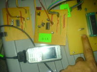
I've also tried the same program with this connection phone---->max232--->max232(again)---->89s51... here's the picture of the experiment


looks like the ATD0125410400 did arrive to the phone...hurmmm.... I think I'll try the connection U suggest too... But I want to know... how can we know the phone data is TTL? any method?


looking forward for replies from all of U... hope it will work... thanx in advance ya....
 

hi friends.... I've already try out saeed's connection.... to my surprise it did as same as when I connected it with the 2 max232... it dial the phone that is commanded to it... however, the program that have work with proteus, still won't work with this connection.... can anybody help me... My presentation date really close by... I wanted to give it a last shot before I call it off... here's the program I've used in proteus... feel free to look at it and any recommendations or suggestions are mostly welcome...
 

Attachments

  • V10.txt
    7.7 KB · Views: 78

from what I can see.... The microcontroller manage to send AT command to handset.... However the microcontroller might failed to do this things...

1. the feedback from the phone did not reach the microcontroller
2. or the microcontroller failed to act accordingly with the feedback of the phone...
 

I've done more search on the internet and done some testing on my own... from what I've found the TX data transmitted by the phone is only 2.68V for logic 1... This explain why the 89s51 failed to act according to the feed back of the phone as 89s51 needs 5V to consider as the signal as logic 1 .... I've found some switching circuit for the TX data of the phone.... I'll done some more testing... hope all went well...
 

Status
Not open for further replies.

Similar threads

Part and Inventory Search

Welcome to EDABoard.com

Sponsor

Back
Top