Continue to Site

Welcome to EDAboard.com

Welcome to our site! EDAboard.com is an international Electronics Discussion Forum focused on EDA software, circuits, schematics, books, theory, papers, asic, pld, 8051, DSP, Network, RF, Analog Design, PCB, Service Manuals... and a whole lot more! To participate you need to register. Registration is free. Click here to register now.

Problem of simulation of BSIM4 model

Status
Not open for further replies.

Yassir_eldo

Junior Member level 2
Joined
Mar 22, 2013
Messages
21
Helped
1
Reputation
2
Reaction score
1
Trophy points
1,283
Visit site
Activity points
1,418
Hello everybody,

I am trying to simulate a CMOS inverter with transient analysis using BSIM4 Berkley Model in ELDO, but the simulation result that I found is a Follower (nearly the same curve than the input). Could anybody tell me why I have this problem with BSIM4v4? I have tried BSIM3v3, some TSMC models, BSIMSOI and I have all the time the inversion result. U find enclosed the schematic that I use.
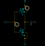
montage.pngmontage.png

Best regards
 

Could you pls. show the netlist which you used for the BSIM4v4 simulation?
 

Hi,

Here is my nitlist: the .cir file. U find enclose a screenshot of the simulation result that I have obtain


curve.png


* Component: $Projet_0/default.group/logic.views/cell_1 Viewpoint: eldonet
.INCLUDE $Projet_0/default.group/logic.views/cell_1/eldonet/cell_1_eldonet.spi
.INCLUDE /home/elbarki/Desktop/models/BSIM4.pmos
.INCLUDE /home/elbarki/Desktop/models/BSIM4nmos
.OPTION NOASCII
.OPTION MODWL
.OPTION ENGNOT
.OPTION AEX

* --- Singles

* - Analysis Setup - Trans
.TRAN 0 150n 0

* --- Waveform Outputs
.PLOT TRAN V(A) V(B)

* --- Forces
VFORCE__A A GROUND PULSE (0 5v 0 0.5e-09 0.5e-09 5e-08 1e-07)
VFORCE___VDD VDD GROUND dc 5v

* --- Libsetup

- - - Updated - - -

Hi,

Here is my nitlist: the .cir file. U find enclose a screenshot of the simulation result that I have obtain


curve.png


* Component: $Projet_0/default.group/logic.views/cell_1 Viewpoint: eldonet
.INCLUDE $Projet_0/default.group/logic.views/cell_1/eldonet/cell_1_eldonet.spi
.INCLUDE /home/elbarki/Desktop/models/BSIM4.pmos
.INCLUDE /home/elbarki/Desktop/models/BSIM4nmos
.OPTION NOASCII
.OPTION MODWL
.OPTION ENGNOT
.OPTION AEX

* --- Singles

* - Analysis Setup - Trans
.TRAN 0 150n 0

* --- Waveform Outputs
.PLOT TRAN V(A) V(B)

* --- Forces
VFORCE__A A GROUND PULSE (0 5v 0 0.5e-09 0.5e-09 5e-08 1e-07)
VFORCE___VDD VDD GROUND dc 5v

* --- Libsetup
 

No, sorry, I thought of your circuit netlist file, which contains the circuit of your inverter, probably this one:
.INCLUDE $Projet_0/default.group/logic.views/cell_1/eldonet/cell_1_eldonet.spi

The (possible) reason: Until BSIM3v3, source & drain of a MOSFET are exchangeable, so the order (D G S B) & (S G D B) were equivalent. If this should have changed with BSIM4 (I really don't know, but layout-dependent reasons could render this necessary), your inverter circuit actually could be a (non-inverting) complementary source follower, if your netlist contains the order (S G D B). Also, the low output voltage of only 4V indicates this.

You could try and falsify or verify this assumption, if you exchange the S & D positions @ both transistors in the netlist (s. above). Then re-simulate (without prior re-netlisting, of course).
 

Status
Not open for further replies.

Part and Inventory Search

Welcome to EDABoard.com

Sponsor

Back
Top