Continue to Site

Welcome to EDAboard.com

Welcome to our site! EDAboard.com is an international Electronics Discussion Forum focused on EDA software, circuits, schematics, books, theory, papers, asic, pld, 8051, DSP, Network, RF, Analog Design, PCB, Service Manuals... and a whole lot more! To participate you need to register. Registration is free. Click here to register now.

problem in serial communication between esp32 and GSM A7670C

Naznee

Newbie level 6
Joined
Mar 21, 2024
Messages
13
Helped
0
Reputation
0
Reaction score
0
Trophy points
1
Activity points
90
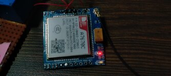
I am using A7670C GSM breakout board with esp32.

Connections

  • RX-TX
  • TX-RX
  • GND-GND
I am giving external power to GSM 3.8 volts according to product description.

When I sent the AT command to GSM module. I don't get output on serial monitor of Arduino IDE.

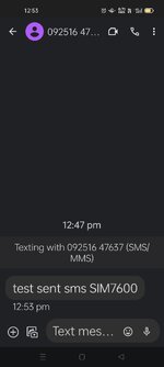
The message is sent to a particular number successfully but I didn't receive the message from mobile.

This is my code

Code:
#include <HardwareSerial.h>
HardwareSerial mySerial(2);
void setup() {
  mySerial.begin(115200);   // Setting the baud rate of GSM Module
  Serial.begin(115200);    // Setting the baud rate of Serial Monitor (Arduino)
  delay(100);
  SendMessage();
  RecieveMessage(); }
void loop() {
  if (Serial.available()>0)
  Serial.write(Serial.read());
   switch(Serial.read())
  {
    case 's':
      SendMessage();
      break;
    case 'r':
      RecieveMessage();
      break;
  }
 if (mySerial.available()>0)
   Serial.write(mySerial.read());
}
 void SendMessage() {
  mySerial.println("AT+CMGF=1");    //Sets the GSM Module in Text Mode
  delay(1000);  // Delay of 1000 milli seconds or 1 second
  mySerial.println("AT+CMGS=\"+91XXXXXXXXXX\"\r"); // Replace x with mobile number
  delay(1000);
  mySerial.println("I am SMS from GSM Module");// The SMS text you want to send
  delay(100);
   mySerial.println((char)26);// ASCII code of CTRL+Z
  delay(1000); }
 void RecieveMessage() {
  mySerial.println("AT+CNMI=2,2,0,0,0"); // AT Command to receive a live SMS
  delay(1000);  }

Other AT commands also don't give me any ok message on serial monitor or any message on serial monitor. I have tried software serial but it doesn't work.
 

Attachments

  • IMG20240320125413.jpg
    IMG20240320125413.jpg
    2.8 MB · Views: 34
  • IMG20240320125728.jpg
    IMG20240320125728.jpg
    1 MB · Views: 34
  • Screenshot_2024-03-20-12-53-47-49_0ce57feeccaa51fb7deed04b4dbda235.jpg
    Screenshot_2024-03-20-12-53-47-49_0ce57feeccaa51fb7deed04b4dbda235.jpg
    176.4 KB · Views: 25
Last edited by a moderator:
HI,

What could go wrong?
* hardware / connections
* voltage levels
* baud rate
* interface setup
* wrong expectation
* wrong code
....
what did you do for debugging these items? What are the results?


Serial.write(Serial.read());
switch(Serial.read())
The first "Serial.read" reads data form the interface.
What data is left for the second "Serial.read"?

Klaus
 
oh sorry there is some code writing issue
this is my correct code


Code C - [expand]
1
2
3
4
5
6
7
8
9
10
11
12
13
14
15
16
17
18
19
20
21
22
23
24
25
26
27
28
29
30
31
32
33
34
#include <HardwareSerial.h>
HardwareSerial mySerial(2);
void setup() {
  mySerial.begin(115200);   // Setting the baud rate of GSM Module
  Serial.begin(115200);    // Setting the baud rate of Serial Monitor (Arduino)
  delay(100);
  SendMessage();
  RecieveMessage(); }
void loop() {
  if (Serial.available()>0)
   switch(Serial.read())
  {
    case 's':
      SendMessage();
      break;
    case 'r':
      RecieveMessage();
      break;
  }
 if (mySerial.available()>0)
   Serial.write(mySerial.read());
}
 void SendMessage() {
  mySerial.println("AT+CMGF=1");    //Sets the GSM Module in Text Mode
  delay(1000);  // Delay of 1000 milli seconds or 1 second
  mySerial.println("AT+CMGS=\"+91XXXXXXXXXX\"\r"); // Replace x with mobile number
  delay(1000);
  mySerial.println("I am SMS from GSM Module");// The SMS text you want to send
  delay(100);
   mySerial.println((char)26);// ASCII code of CTRL+Z
  delay(1000); }
 void RecieveMessage() {
  mySerial.println("AT+CNMI=2,2,0,0,0"); // AT Command to receive a live SMS
  delay(1000);  }


I don't get any response from GSM module .I tried one more thing that when mySerial was available I read the data from this and save this in buffer and send this buffer to me by send_message() I got blank messages on my phone.
 
Last edited by a moderator:
The code looks OK to me but I have some concerns about
" mySerial.begin(115200); // Setting the baud rate of GSM Module"

It looks like you intend to set the bauds rate of the GSM unit to 115200 but if it isn't already that speed it will ignore the data. Check the data sheet (I do not have it here) and see if the default rate for the GSM unit is already 115200, it may start at say 9600 until reconfigured. It might help to swap the two ".begin" lines so you are sure the Arduino serial is at 115200 (or whatever the GSM expects) before communicating with the GSM module.

Brian.
 
Hi,

to me the code is not OK.

It still has the same problem as I´ve already mentioned in post#2.

There twice is "Serial.read()".
* So on one RED the incoming data is processed but not echoed back
* and on the other READ the data is echoed back but not processed.
.. with random order which byte is processed or echoed. It even my be that 3 bytes in a row become echoed but only one is processed. Inconsistent behaviour.

***
Also:
* mySerial.begin(115200); // Setting the baud rate of GSM Module
* Serial.begin(115200); // Setting the baud rate of Serial Monitor (Arduino)

I don´t know how the compiler works. But for me it is not clear which UART is used by which object. Let´s assume there are 3 UARTS and one wants to use UART3 for the mySerial and UART3 for the Serial object.

***
OP does not want to give feedback about all the worries and questions in post#2. Thus I guess he´s not interested in my assistance..

Klaus
 
The code looks OK to me but I have some concerns about
" mySerial.begin(115200); // Setting the baud rate of GSM Module"

It looks like you intend to set the bauds rate of the GSM unit to 115200 but if it isn't already that speed it will ignore the data. Check the data sheet (I do not have it here) and see if the default rate for the GSM unit is already 115200, it may start at say 9600 until reconfigured. It might help to swap the two ".begin" lines so you are sure the Arduino serial is at 115200 (or whatever the GSM expects) before communicating with the GSM module.

Brian.
thank you for the reply but can you explain me more ?what should I change in my code ?can you give me changed code lines?
 
Hi,

to me the code is not OK.

It still has the same problem as I´ve already mentioned in post#2.

There twice is "Serial.read()".
* So on one RED the incoming data is processed but not echoed back
* and on the other READ the data is echoed back but not processed.
.. with random order which byte is processed or echoed. It even my be that 3 bytes in a row become echoed but only one is processed. Inconsistent behaviour.

***
Also:
* mySerial.begin(115200); // Setting the baud rate of GSM Module
* Serial.begin(115200); // Setting the baud rate of Serial Monitor (Arduino)

I don´t know how the compiler works. But for me it is not clear which UART is used by which object. Let´s assume there are 3 UARTS and one wants to use UART3 for the mySerial and UART3 for the Serial object.

***
OP does not want to give feedback about all the worries and questions in post#2. Thus I guess he´s not interested in my assistance..

Klaus
I am using esp32 so there are 3 UART . UART1 is used for uploading code and for serial output by TTL and UART2(GPIO16,GPIO17) is for serial communication between GSM and ESP32
*****these Serial read for when I will r or s in my serial monitor to read them .
if (Serial.available()>0)
switch(Serial.read())
{
case 's':
SendMessage();
break;
case 'r':
RecieveMessage();
break;
}
******this one is for when gsm is available to read the data and write it on serial monitor
if (mySerial.available()>0)
Serial.write(mySerial.read());
}
 
Klaus is correct (as always :)) but the point I made earlier is valid.
Sending a command to the GSM module to tell it what speed to communicate at is pointless, it won't see the command if the speed doesn't match the ESP32 UART baud rate already.
Code:
  mySerial.begin(115200);   // Setting the baud rate of GSM Module
  Serial.begin(115200);    // Setting the baud rate of Serial Monitor (Arduino)
As Klaus states, it depends on which UART you are connecting to but I suggest setting the Arduino baud rate before the GSM one. Are you using an ESP32 or a development board with USB interface, if the latter you might have a clash of serial ports with the on-board USB IC.

Brian.
yes I am using esp32 with FTDI coverter for uploading code and serial output and UART2 for GSM and esp32 Serial communication
esp32 works on 9600 and 115200 both .
 
if (mySerial.available()>0)
Serial.write(mySerial.read());
My fault. The names are so similar ... I mixed them up.
So in this regard you code seems to be correct.

I´m sure YOU know how to read your code. But for us it´s much more complicated.
Thus we recommend
* to COMMENT your code. Just to show (us) what this line is meant to do.
* And to use more meaningful names.
* to use varaibles (with meaninful names, like gsmSerial instead of mySerial)
* to use directives instead of hard coding

******
I´m not sure how the compilter treats the different UARTs.
But with ESP you could use "xxxSerial.begin ( baudRate, config...)", where you can specify the UART Rx and Tx pins. So YOU define which UART is used.

****
And please use C O D E tags when posting code. Or simply press the [ C O D E ] button to include your code.

Klaus
thank you for the reply .I founded the problem that my GSM module need 1.8 V at RX and TX for operation but I was giving 3.2 at RX and 1.8 at TX . In code the the you mentioned also a correction. I am trying to give 1.8V to both RX and TX then I will try my code
 

LaTeX Commands Quick-Menu:

Part and Inventory Search

Welcome to EDABoard.com

Sponsor

Back
Top