Continue to Site

Welcome to EDAboard.com

Welcome to our site! EDAboard.com is an international Electronics Discussion Forum focused on EDA software, circuits, schematics, books, theory, papers, asic, pld, 8051, DSP, Network, RF, Analog Design, PCB, Service Manuals... and a whole lot more! To participate you need to register. Registration is free. Click here to register now.

Problem in sending signal from RF MODULES

Status
Not open for further replies.

Laxman Kumar

Junior Member level 1
Joined
Jan 19, 2014
Messages
17
Helped
0
Reputation
0
Reaction score
0
Trophy points
1
Visit site
Activity points
123
I AM working on a project called wireless metal detector
i have one pare of ht12e encoder and ht12d decoder and RF MODULES
when i am sending data from RF transmitter it properly sends the data to reciever...but
i want that when metal detector detects the metal one one signal shuld be send through RF transmitter so that other reciever side i recieved that signal and do something for indication like led glow...i have attached the metal detector circuit diagram i am using.....i have checked that when it detects metal 555ic pin 3 goes high and low high and low.....i tried to connect that pin with encoder but from there i am not getting any signal to reciever....how to do that help me plss..i am noob in electronics.....


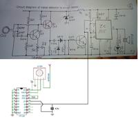
metal.JPG
 

One best way is to remove the 555 ic and all its relevant components from your circuit, because you don't need that anymore since you are using a transmitter module. Connect the collector pin of 3rd BC547 (currently with pin 3 of 555) with your encoder pin. Keep TE enabled. See if it works...
 

That 555 timer is fixed with metal detector if removed that one how that circuit will work????
 

That timer ic is used just to trigger the buzzer. It doesn't have any role in 'detecting' metal'. I guess you don't need any buzzing sound or LED in the metal detector. You may need that on the receiver end!!!

When you detect any metal with the detector, the 3rd BC547 stops shunting pin 4 of timer to ground, thus disabling the reset. (I mistakenly wrote pin 3 in my previous post). A timer calculator says the 555 is configured for around 4.8Hz. You no need to feed that signal to encoder. You will get your signal directly from the 3rd BC547.

As you said "555 timer is fixed with metal detector", I guess you cannot modify it?? Just for testing, take a connection from pin 4, add any electrolytic cap with it w.r.t ground, and feed that connection to your encoder (any of D0 to D3) for transmission.

Hope you got it???

(add any electrolytic cap with it w.r.t ground,)

I didnt understand this one what does this mean????
 

I am talking about this... That capacitor isn't compulsory, but just to filter any oscillations if exist. Give it a try and see if it works...


I am talking about this... That capacitor isn't compulsory, but just to filter any oscillations if exist. Give it a try and see if it works...


no not working
how about this...my friend told me
Take pin 3 from
metal detector, give to base of transistor with 10k resistor. emitter
is grounded. connect RF trasmitter pin to collector. then collector
is connected to 5v with a 10k resistor.
iYMO8.png

- - - Updated - - -

no it does not work
how about this...my friend told me about this

Take pin 3 from
metal detector, give to base of transistor with 10k resistor. emitter
is grounded. connect RF trasmitter pin to collector. then collector
is connected to 5v with a 10k resistor.

iYMO8.png
 

It will work same, the fact is the circuit you showed will act as a NOT gate. It will just invert the signal. You will find your 'output' as logic high all the time, except when it detects a metal.
Resistor values are ofcourse not critical, but 10k will be little high. Use 4.7k at most. Have you tried this circuit???

Referring to the setup I showed in my post, I want you to check the voltage level at pin 4, with metal & without metal near the coil. Compare the voltage level with buzzer sound....
 

Not able to work with 2 RF modules

i am working On a project where i am sending signal from pc to a ROBOT car by RF modules(433mhz) ..transmitter is connected to my pc by microcontroller and reciever is on car..
and there is one more pair of RF module(433mhz) whose trasmitter is on ROBOT car and Receiver is connected to my pc through microcontroller..
BUT problem is that when i am switching on both RF module then non of them are working....If i am switching off one RF module then other is working vice versa..
what is the problem...????
 

Re: Not able to work with 2 RF modules

You are probably sending permanently with both modules. In case of simple ASK modules, an high idle level of the TX signal (e.g. when directly connected to a µC UART TX pin) will achieve this. You can try with inverted TX/RX on both sides. Simple ASK modules are however not well suited for transmission of UART signals without modification.

If you circuit already uses suitable TX polarity, the problem might be that the µC is sending data without a rest.

sorry I didnt get U..Sending permanently means...what does it mean by Inverted TX/RX on both sides...
can u pls tell me some detail...
Bcz i am not goot in electronics...
 

Re: Not able to work with 2 RF modules

You should start with some details about the involved modules and how they are connected to the processor.
 

Re: Not able to work with 2 RF modules

You should start with some details about the involved modules and how they are connected to the processor.

IF i replace One RF module (433mhz) with 315mHz will it work??????
 

Re: Not able to work with 2 RF modules

Most likely yes, but basically a reasonable transmission schedule should help as well.
 

Re: Not able to work with 2 RF modules

Sending permanently means that the transmitter is always transmitting a RF carrier, even if you are not sending data to the transmitter module. When you have 2 transmitters on, the RF carriers interfere with each other. Unless you have a way to turn the RF carrier on and off, the only way you can have 2 transmitters on at the same time would be using 2 different frequencies. One at 433 MHz and the other at 315 MHz should work. If you can provide more details on the transmitting modules, that would help.

My project is PC controlled car with metal detector...
so i am sending signal from my pc to car by Transmitter with HT12e.... and receiver with HT12d decoder is connected to motor driver for movement..
and 2nd RF module is there whose transmitter with encoder is there on car and receiver is on my PC side( receiver is connected only with one led)..
2nd module work is to transmit signal when any metal detected...and receiver side led will glow...
when metal detects then 5v power is going to 2nd transmitter's encoder 1st pin..and on receiver side led is connected to same first pin by which led is glowing...
 

Re: Not able to work with 2 RF modules

What about the RF portion? The 433 MHz and 315 MHz transmitters? Those are what appear to be the problem.
 

Re: Not able to work with 2 RF modules

If you are employing microcontrollers at both endpoints, the car and interfaced to the PC, have you considering using transceivers like the Nordic nRF24L01+.

As they are transceivers they are bidirectional, 2.4GHz ISM band, offer up to 2Mbps data rates, standard SPI interface, low power modes for battery operation and handle encoding/decoding internally.

Nordic Semiconductor nRF24L01+

A pair of nRF24L01+ modules are regularly available on eBay in the $2 to $3 range.

eBay Search - nRF24L01+

There are several open source libraries available for many of the popular microcontrollers.


BigDog
 

Re: Not able to work with 2 RF modules

I realize that. What about the part number, spec, etc? Basically, I'm asking to see if there is a way to turn the transmitter off or is it constantly on. BigDog gave a good alternative as well as those modules can be transmit and receive at the same time so you don't need to turn the transmitter off.
 

Status
Not open for further replies.

Part and Inventory Search

Welcome to EDABoard.com

Sponsor

Back
Top