Continue to Site

Welcome to EDAboard.com

Welcome to our site! EDAboard.com is an international Electronics Discussion Forum focused on EDA software, circuits, schematics, books, theory, papers, asic, pld, 8051, DSP, Network, RF, Analog Design, PCB, Service Manuals... and a whole lot more! To participate you need to register. Registration is free. Click here to register now.

Pressure Sensor with current source of 1.5mA?

Status
Not open for further replies.

nick703

Advanced Member level 1
Joined
Oct 17, 2011
Messages
422
Helped
21
Reputation
44
Reaction score
22
Trophy points
1,298
Location
surat
Activity points
3,987
Hello Friends ,
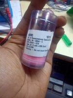
I have a Pressure sensor of MEMS 5PSI. below is the datasheet link.
https://www.te.com/commerce/Documen...6CA6pdfEnglishENG_DS_86C_A6.pdf86-005A-C

TE Pressure sensor.png


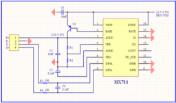
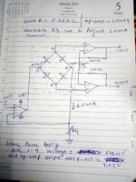
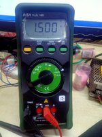
So my first question is can i provide 5 voltage input throw 3.3Kohm resistor to get 1.5mA curretn source in pin 3 and 2.
or other solution required.
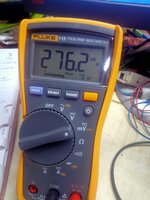
and second question is datasheet mention 100mV output at full span of pin no. 1 and 4. but when i measure i got atmosphere pressure level give me 168mV output.
please give me guide regarding output span.
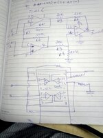
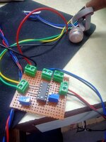
i have also make circuit using lm324 quad op-amp but circuit didn't give me 3.012V span?
so please help me.
 

Hi,

I don´t think it´s a MEMS sensor. I rather think it´s a strain gauge sensor.

1) No. It´s typical input resistance is 5kOhms (2.5k ... 6.5k). So for 1.5mA you typ. have 7.5V across the sensor.
--> impossible with a 5V supply.

2) How did you measure this? ... since in question 1 you ask how to power it...
I doubt your measurement.

3) You´ve already mentioned the 100mV output span. What exactly are you asking for?

4) LM324 isn´t the best choice. Why not using an INAMP / INA?
You said you made a circuit .... but don´t show. So we can´t validate this. Also we can´t validate whater your power supply is suitable.
And you say "you don´t get 3.012V", but you again did not say what you get instead? maybe 3.011V ???

Klaus
 

hello KlausST

Thanks for your replay,
I have power the +Sup and -Sup pin to Hx711 module pin of E+ and E-. below is the circuit module of hx711.


Now second part with output pin of 1 and 4 i have simply connect using lm324 opamp as per instruction manual.

Yes i measure the voltage and the output i get is pin 1 and 4 with reference of atmospheric pressure i got value is 168mVolt and when i used opamp output pin 1 and 7 the circuit voltage i got 4.1 v .


Please give me suggest circuit for best result.
i just want only my pressure sensor give me the output 0-100mV span and ampliify this to 0-5V signal level.
is that any signal conditioner circuit can i use please suggest.
 

Attachments

  • hx711 power supply.png
    hx711 power supply.png
    160.7 KB · Views: 133
  • WhatsApp Image 2022-03-02 at 7.31.35 PM.jpeg
    WhatsApp Image 2022-03-02 at 7.31.35 PM.jpeg
    78.2 KB · Views: 141

Hi,

I have more questions than before...

I don´t know what +SUP and -SUP is. Can´t find them in your schematics, nor can I find any values.

Now you show two circuits. Why? Which one did you use?
R1 value is missing. Since this is a standard "instrumentation amplifier circuit" there should be documentation how to calculate R1. R1 is for gain setting. Gain = V_out / V_in = 3.0V / 0.1V = 30.

What "instruction manual" are you talking about?

Klaus
 

Hi

+Sup and -Sup is the current source supply.

First circuit is use only for power the sensor and the second circuit is the measure the output.

As i mentioned datasheet of my pressure sensor below is the link
https://www.te.com/commerce/Documen...6CA6pdfEnglishENG_DS_86C_A6.pdf86-005A-C

In above datasheet page no. 4 You find schametic using opamp as suggested by manufacture reference.
I have a simply use opamp as per circuit discribed right. and also R1 is the internal gain of sensor pin no. 5 and 6 which is 6.46Kohm i measured.

if am i wrong then please tell me brother.
 

Hi,

I don´t understand:
The pressure sensor datasheet says you should use a 1.5mA current supply. HX711 does not provide a 1.5mA supply.
If you don´t follow the datasheet you don´t get the same results as specified in the datasheet.

You are right: R1 is inside the sensor.

Just to avoid misunderstanding: With "instruction manual" you meant the "sensor datasheet". Please confirm.
(I mean there is a difference between datsheet and instruction manual. And there may be the Hx711 datasheet, the LM324 datasheet...)

Klaus
 

Although the pressure sensor is specified for constant current supply, you can also use constant voltage, e.g. 5V supply, but you can expect higher span temperature drift.

Alternatively, you can supply it with lower constant current, e.g. 0.5 mA. But you need to design an electronic constant current source. If this is over your head, constant voltage is probabbly a better choice.
 

Sorry Kluas for misunderstanding of my fault.
Thank Fvm for clarifying to constant current source use.
And one question is constant voltage should i apply direct to resistive bridge?

Actually i didn't understand regarding sensor output that's why i am confused. Because pressure sensor manual say full span voltage output is 100mV. So as per my understand sensor output is not exceed to 100mV + some tolerance right. Please clarify me.
Tomorrow i will check with constant current and amplify signal using opamp. And testing using my device.
 

Hi,

While constant voltage surely is possible you not only have to expect degraded performance but also the internal span resistor (gain set resistor) is almost useless.

Span: is given in the datasheet: typ: 100mV
and the tolerance also is given as the span can be in the range of 50mV ... to 150mV. (+/- 50%)
To compensate for this huge tolerance they use the "gain set resistor" which sets the tolerance to +/-1%.

Could you please give the exact part number of your sensor?

Klaus
 

Hi,

So this is an absolute pressure sensor for tge range of 0...5psi.
Nominal air pressure is around 15psi.
This means at nominal air pressure it is out of range.

The sensor's output is
* nominally 0mV at vaccuum
* 100mV at 5psi
* out of nominal range at nominal air pressure (14.7 psi)

This explains why you see 168mV .. even when not powered properly.

Klaus
 

Ok i have a test below circuit and this circuit i have set current 1.5mA and got the output is 276.2mV and via opamp- i got nearly 7.02V of Out+ and Out-.

i think something wrong because 1.5mA sensor output is calibrated 95.5mV why i am getting 272.6mV?

is that possible atmosphere pressure is 14.7psi that's why i getting 272.6mv ?
but sensor is 5 psi for 95.5mV is am i correct or wrong? Please guide me.
 

Attachments

  • WhatsApp Image 2022-03-03 at 1.32.28 PM.jpeg
    WhatsApp Image 2022-03-03 at 1.32.28 PM.jpeg
    161.3 KB · Views: 146
  • WhatsApp Image 2022-03-03 at 12.52.41 PM (2).jpeg
    WhatsApp Image 2022-03-03 at 12.52.41 PM (2).jpeg
    173.2 KB · Views: 135
  • WhatsApp Image 2022-03-03 at 12.52.41 PM (1).jpeg
    WhatsApp Image 2022-03-03 at 12.52.41 PM (1).jpeg
    140.6 KB · Views: 119
  • WhatsApp Image 2022-03-03 at 12.52.41 PM.jpeg
    WhatsApp Image 2022-03-03 at 12.52.41 PM.jpeg
    197.1 KB · Views: 161

Hi,

Yes, this is how the sensor works. (did you read post#11?)
well done:
* 1.5mA is correct
* 7.02V makes sense

Issues:
* I wonder how this can be, because your schematic shows 5V across the shunt plus 7.02V across the sensor gives 12.02V at OPAMP output. This is impossible with a 12V supply as shown.
* you say "Out+" and "Out-" but I don´t see this in your schematic. To avoid confusion please use the identical terminology in schematic and text.
* Your voltmeter is set to AC, while you want DC. Please correct this.
* two times you wrote 272.6 instead of 276.2. This makes a difference.

Mathematics:
The sensor gives 95.5mV for 5psi.
so 276.2mV * 5psi / 95.5mV/psi = 14.46psi
it´s just 1.63% off the expected value @14.7psi.

So this is rather close to to what one may expect.
Mind: The sensor is way overloaded. It is designed for 5psi while you use it at more than 14psi!
Thus it´s quite normal that you see increased error.

Klaus
 
Last edited:
Absolute pressure sensors (measuring difference between externally applied pressure and an internal vacuum reference) must withstand normal athmospheric pressuce of 1013 mB/14.7 psi, otherwise it would be impossible to handle them. In case of a passive strain gauge sensor, we can also expect a monotone transfer characteristic, but not not necessarily linearity up to to this pressure range. It's unlikely to get a specification for the overpressure range.
 

Hi
yes i read your post #11. as per your suggest i completely making this circuit.
yes for my typing mistake i got 276.2mV is correct.

I wonder how this can be, because your schematic shows 5V across the shunt plus 7.02V across the sensor gives 12.02V at OPAMP output. This is impossible with a 12V supply as shown.

sorry for mistake of my measurement to snap AC in voltmater.
latest measurement give me the reading of sensor output is 276.2mV and this output is amplify using opamp give me reading of 6.85V not 7.02V. Now 12V condition satisfied right.

ok this is a rough method right .
No i want precision . so please give me a guide to choose right op amp for give me output of 0-100mV to 0-5V dc for analog reading.
or can i directly connect this type sensor output to ad7193 24-bit sigma -delta adc?

please guide me.
--- Updated ---

Absolute pressure sensors (measuring difference between externally applied pressure and an internal vacuum reference) must withstand normal athmospheric pressuce of 1013 mB/14.7 psi, otherwise it would be impossible to handle them. In case of a passive strain gauge sensor, we can also expect a monotone transfer characteristic, but not not necessarily linearity up to to this pressure range. It's unlikely to get a specification for the overpressure range.

Hi FVM
thanks for reply pressure manual say Pressure Overload x3 rated and pressure Burst is x4 rated.
 

Yes, I've seen the range spec. In my understanding, it doesn't say anything about accuracy in overload range. Reference for error amount is straight line 0 to 5 psi.
 

Hi,

most important question:
Do you really want to use this sensor at pressure close to vacuum? --> 0...5psi absolute

You want precision or accuracy or both?
What is your max allowed error for prec/acc? (Value, please. No text)

Supply:
6.5k (max) @ 1.5mA gives 9.75V (max)
plus 5V at the shunt = 14.75V
--> thus you need at least 15V supply.
(While 12V works with your sensor, it does not mean it works with a different sensor of same type)

Accuracy:
The "killer" for accuracy in your case is the offset voltage of the OPAMP.

Precision:
The "killer" for precision in your case is: Opamp offset drift and noise.
--> HF noise should be reduced by using low pass filters.

Stability:
* 1.5mA Supply: I strongly recommend to use local feedback for the OPAMP to maintain stability even for longer wires.
* Instrumentation amplifier: the same local feedback here, especially because of the wiring to the "gain set resistor"

generally:
* Use a bulk capacitor for each supply rail. Use a ceramics capacitor for each supply pin of each IC.
* Use ESD protection at sensor lines.
* Use HF filter at Instrumentation amplifier inputs.
* use a solid ground plane

AD7193:
You may use it. (For my taste it is overkill: Don´t expect an accuracy or precision better than 16 bits)
You say 0...5V signal range.
Now if you want to be somehow accurate and precise you must not use VDD as reference --> you need an external reference voltage.
If you want to use an 5.00V precise reference then you need to satisfy that VDD is higher than this.
So what´s your supply voltage then (range!)

Klaus
 

most important question:
Do you really want to use this sensor at pressure close to vacuum? --> 0...5psi absolute
Yes i do, because i have a chamber and i have already have sensor of 0-15 psi but this sensor output is 0-10v . so my system i didn't required any other circuit i have directly fed this signal to my adc and read the appropriate pressure. So now i have to change sensor because of shortage in market. so i find this sensor. so my answer is yes i want to use this.

You want precision or accuracy or both?
What is your max allowed error fpr prec/acc? (Value, please. No text)
yes i want both because amplify the signal required more stable voltage to input. and maximum 0.02 psi error required for my system.

Supply:
6.5k (max) @ 1.5mA gives 9.75V (max)
plus 5V at the shunt = 14.75V
--> thus you need at least 15V supply.
(While 12V works with your sensor, it does not mean it works with a different sensor of same type)
yes no problem i can use 15v power supply.

Accuracy and Precision:
thats why i want know which is best opamp for my application.

Stability:
* 1.5mA Supply: I strongly recommend to use local feedback for the OPAMP to maintain stability even for longer wires.
* Instrumentation amplifier: the same local feedback here, especially because of the wiring to the "gain set resistor"
i didn't understand this can you please give me more detail of local feedback. my method for generating current is stable or not?


generally:
* Use a bulk capacitor for each supply rail. Use a ceramics capacitor for each supply pin of each IC.
* Use ESD protection at sensor lines.
* Use HF filter at Instrumentation amplifier inputs.
yes i do for stability of power source and input pin.

and last Ad7193 i will try later but main focus is right now is to do using opamp .
 

The post #12 circuit can basically work. Personally, I would 1. scale down the input reference and shunt voltage drop to e.g. 1 V and 2. reduce the excitation current to 0.5 or 1 mA to adapt the full scale output to the larger pressure range.

Achievable linearity in "overpressure" range must be evaluated empirically.
 

Hi,
yes i want both because amplify the signal required more stable voltage to input. and maximum 0.02 psi error required for my system.
0.02psi on a 5psi span is 0.4%
zero pressure output is +/-2 mV this is 4mV or 4% or 0.2psi --> this is ten times your requirement!
Sensor nonlinearity is +/-0.2% --> this already is 0.4%
then you have a +/-0.25% drift per year
additionally Temperature drift in span and offset..
additionally OPAMP circuit error for both power supply and amplification

--> So your requirement is impossible to achieve with this sensor. You need to adjust your requirement.
Please do some error calculations on your own.

Sensor output span is 100mV (nom) so 0.4% are 0.4mV. --> OPAMP circuit input offset voltage including offset drift need to be way below this 0.4mV.

LM324 is not specified with noise. I can only guess why. Better use an OPAMP with specified noise.

Klaus
 
Status
Not open for further replies.

Similar threads

Part and Inventory Search

Welcome to EDABoard.com

Sponsor

Back
Top