Continue to Site

Welcome to EDAboard.com

Welcome to our site! EDAboard.com is an international Electronics Discussion Forum focused on EDA software, circuits, schematics, books, theory, papers, asic, pld, 8051, DSP, Network, RF, Analog Design, PCB, Service Manuals... and a whole lot more! To participate you need to register. Registration is free. Click here to register now.

precise peak detector

Status
Not open for further replies.

nima_1981

Member level 3
Joined
Apr 22, 2010
Messages
61
Helped
0
Reputation
0
Reaction score
0
Trophy points
1,286
Location
Ocean Mind
Activity points
1,877
Hi friends ,
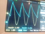
I have 100 mV to 3 V Ac signal with 700 Hz frq and i should to measure the rms value with Mirocontroller (Avr -BasCom) then i use this circuit but that is very big error that you can see in attached picture , please help me for find best method to convert Peak Voltage to Dc value .
Thanks

Ashampoo_Snap_2016_11_09_02h44m12s_003_.png

sin.jpg
 
Last edited by a moderator:

Your problem may be due to the very heavy loading on the output (10uF + 10K). The op amp will struggle to keep that load charged right up at the actual peak.

Try it with a much smaller capacitor, say 100nF and a 1 meg load, the time constant will be the same.

If the real output load must be 10K, then fit a unity gain buffer on the output of the above circuit.
 
Thanks Warpspeed
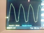
I try your suggestion Cap & Res but i have not Dc now ? see this picture
sin 3.jpg
 

You are using a x1 probe which is also loading the circuit.
Try using a x10 probe and remove the 1 meg load resistor from the circuit.
 
Remove R1 that is quickly discharging the 100nF capacitor C1. Then the 1M for RL will slowly discharge the 100nF capacitor.
 

Hi,

Use the scope and measure directely the output of the opamp. Then you see what's happening.
I recommend to use a second diode from output to inverting input. Cathode to the output.

This should prevent the opamp output from saturation.

Maybe this can solve the problem. But I'm not sure.

Klaus

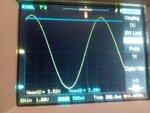
Dear i use another diode and use oscope for directly measurement , but as you see in picture they are not equal , did you have another method for convert sin wave to dc for measurement?
 

It's not desirable to use peak detection to determine the RMS value of a sinewave, due to its sensitivity to small amounts of noise and waveform distortion.
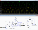
Here's a precision full-wave rectifier circuit with an output 2nd order filter that has its gain selected to give a DC output equal to the RMS value of the waveform average value.

(But if you need the true RMS value then you could take many samples of the waveform (20 or more per cycle) using the processor A/D converter, and then calculate the root-mean-square value of the samples.)

Full Wave Rectifier.PNG
 
Status
Not open for further replies.

Similar threads

Part and Inventory Search

Welcome to EDABoard.com

Sponsor

Back
Top