Continue to Site

Welcome to EDAboard.com

Welcome to our site! EDAboard.com is an international Electronics Discussion Forum focused on EDA software, circuits, schematics, books, theory, papers, asic, pld, 8051, DSP, Network, RF, Analog Design, PCB, Service Manuals... and a whole lot more! To participate you need to register. Registration is free. Click here to register now.

[SOLVED] preamp design for broadcast am receiver

Status
Not open for further replies.

krazyfencer

Junior Member level 2
Joined
Aug 5, 2013
Messages
23
Helped
0
Reputation
0
Reaction score
0
Trophy points
1
Location
East Coast, USA
Visit site
Activity points
266
Hello,

I am trying to make a superhet broadcast receiver. I had a few questions about the preamplifier. Here is roughly what I am thinking:
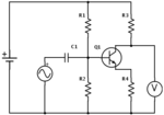
preamp.png

1) What amount of gain should I be aiming for in the preamp?
2) Is it worth chaining multiple transistors in the preamp to get a large gain, or does this make the noise figure insanely large?
3) When choosing a transistor for Q1, would something like a 2N3094 work for broadcast am (say 560kHZ to 1600kHZ)?
4) For a transistor, am I basically looking for anything where the data sheet puts the max frequency as an amplifier above the input frequency I care about, and some noise figure that doesn't seem giant? Are there other factors to worry about?

Thanks for bearing with me, radio is cool (once I figure out how to do it)!
 

1. depends on the receiver design but probably very low.
2. you can chain them but both the noise of the amplifiers and other noise sources will also increase. You really need to aim for best 'signal to noise' ratio than just high gain.
3. yes, maybe not the best but far from the worst.
4. aim for a transistor with an fT (transistion frequency) at LEAST twice the highest frequency you are working at. Generally speaking, higher is better but in any case you would find it difficult to find a modern transistor with an fT low enough to worry about anyway.

Your real problem with that design is that your radio almost certainly has a very low input impedance, maybe only a few 10's of Ohms. That configuration of amplifier works best when the load on it is very high impedance. The mismatch will drop the available signal level by maybe 95% or more and any gain from the transistor will be lost. You might even get out less than you put in! Do some research into 'common base' configuration, it has a low input impedance (good match to your antenna) and a lower output impedance giving a better match to the radio. It also tends to be more stable at radio frequencies.

Brian
 
Thanks! How do I calculate the input impedence? Is it the impedence from the antenna (ac source) to the base of the transistor? Is this just a function of R1 and R2? I've heard that I want to match input and output impedances in radio circuits to minimize power loss, and I get how to calculate the net impedence (at a certain frequency) for the whole circuit, but I don't understand how to divide it up into input and output impedances.
 

The gain of your circuit is R3/R4, it is better to split R4 into two parts, one part to determine the collector current and decoupled with a capacitor which has a low impedance at the working frequency, say .1 MF and leave a low value - 22 ohms? undecoupled, this will reduce the gain slightly but will make the stage a lot more linear. As said its best to follow this amplifier with a emitter follower, which will have a gain of .95 or more (slight loss) but will be able to feed a low input impedance aerial input of a receiver. Do not worry about the noise factor of the input transistor on AM as the noise picked up by the aerial will exceed this figure. Just run the transistor at about 1mA current. Just thought, the decoupling capacitor that I mentioned, could have a 5K pot wired in series with it and earth, so if you have a strong signal you can reduce the gain of the pre-amp by putting more resistance in series with the cap.
Frank
 

krazyfencer
Given that your Antenna will likely have a low impedance, you could look at the option of a Common base amplifier circuit with a second stage of an emitter follower to have a low impedance output as well.
Some info here on the Common base amplifier circuit: https://www.radio-electronics.com/info/circuits/transistor/common-base-amplifier-configuration.php, there are many other descriptions of this type of circuit on the 'net as well.
Input and Output Impedances can then be calculated, with relevant info from websites.
You will also need to apply something to limit voltage spikes from your Antenna such as 'back to back' diodes across your input.

You may also find that some band filtering is useful between your Antenna and the Pre-Amplifier Input to reduce 'unwanted' strong signals from overloading your circuit.

hope this assists
Mik
 
@audiomilk: That site is exactly what I was looking for, thanks!

So you are saying that the common-base amplifier has a low input impedance that I can match to the antenna. But the amplifier also has a high output impedance, right? So you are saying that you want to use an emitter-follower to match the high output impedance and bring it down to a low impedance output. Right? So is the overall idea of impedance matching that output of stage X must match the input of stage X+1 (for all stages), or that *all* input and output impedances of every stage must be the same?
 

They don't have to be the same (and rarely are) but maximum signal power is conveyed when the impedances match each other. When a single frequency is being used the usual method is to use transformer matching which allows high gain and good match at the same time but in a tunable receiver it would be very difficult to implement because the values are different for each frequency. If you look at the IF amplifier stages of a superhet receiver you will notice they usually use common emitter amplifiers like the one in your first post but have a transformer coupling in and out of each stage to match the impedance. This is fine in an IF amplifier because the transformers are tuned to a fixed frequency but you wouldn't want several tuning controls to keep in line with each other to sweep across the band. There ARE designs for tunable pre-amps which use dual or even triple gang variable capacitors but they are notoriusly difficult to construct and the capacitors are expensive and hard to find.

Brian.
 
Thanks everybody! I think it will take a while to wrap my head around all of this, but I think my original question is solved. I'm going to look into using the common-base configuration and focus on getting my impedances matched. It will probably take a while :) Thanks again!
 

All AM radios have AGC (automatic gain control) of the RF amplifier and sometimes the IF amplifier so that a strong local station does not overload the radio and so the volume level is the same for a strong local station and a weak distant station.
The preamp should have tuning on its input and maybe on its output.
 

Status
Not open for further replies.

Similar threads

Part and Inventory Search

Welcome to EDABoard.com

Sponsor

Back
Top