Vermes
Advanced Member level 4
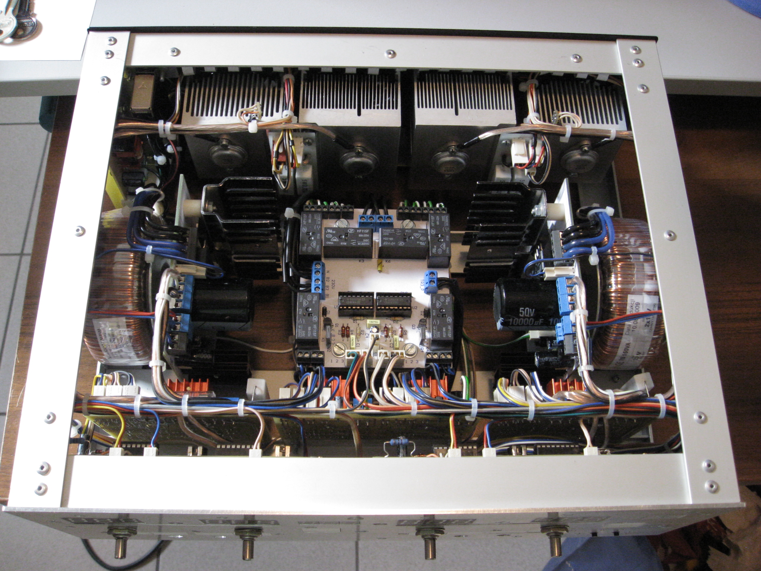
In fact, this are two power supplies in one housing, but they can be connected serially to gain bigger tension or pseudosymmetry treating the connection as ground.
Construction
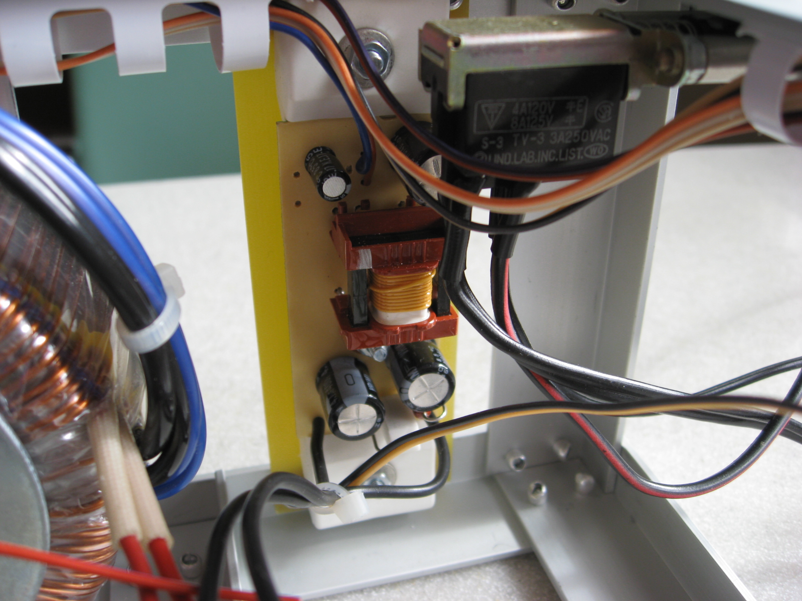
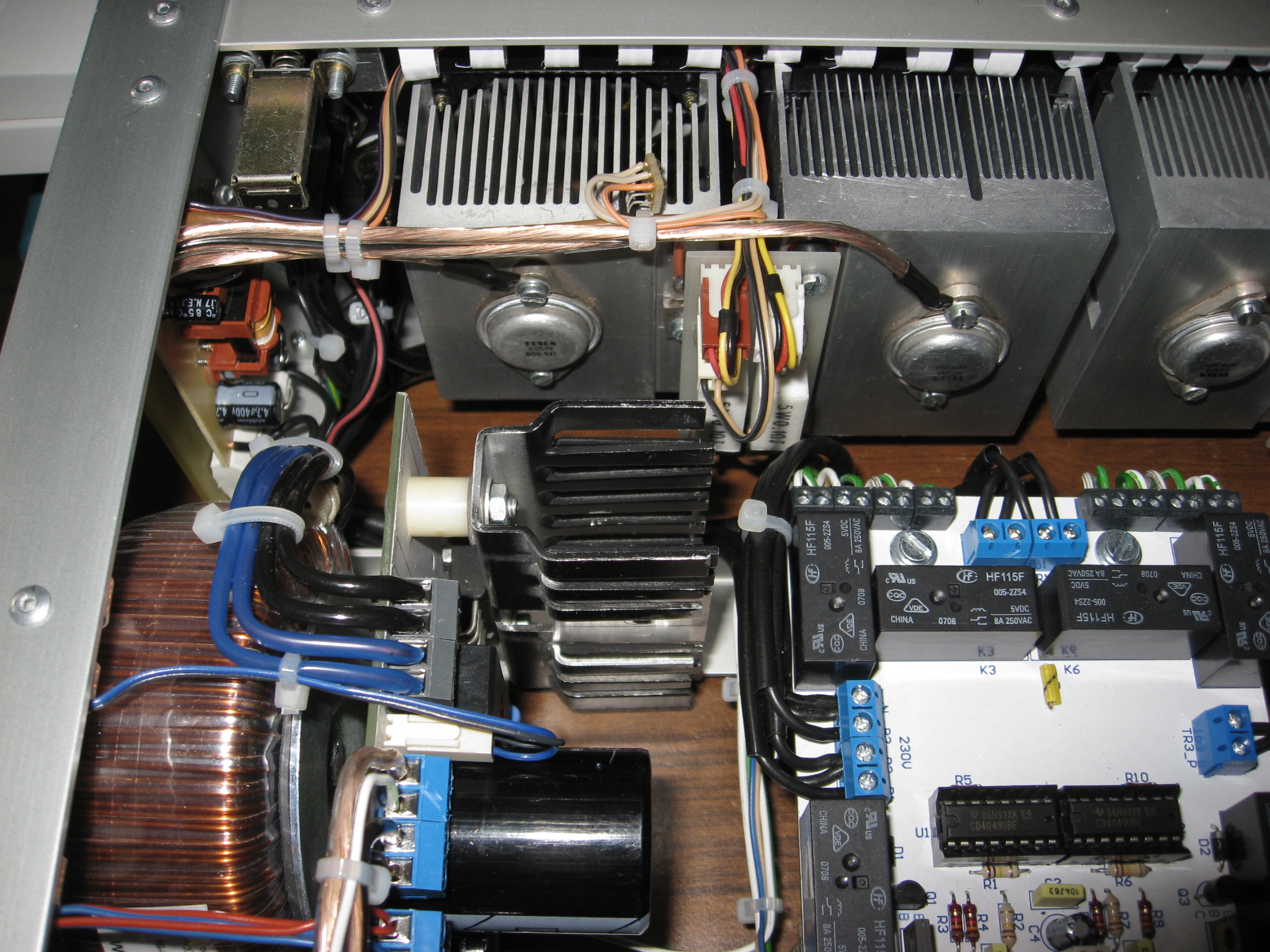
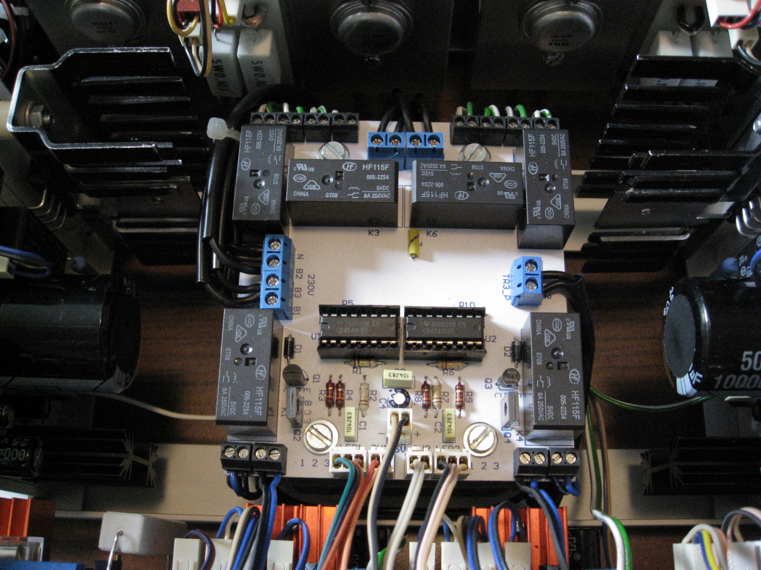
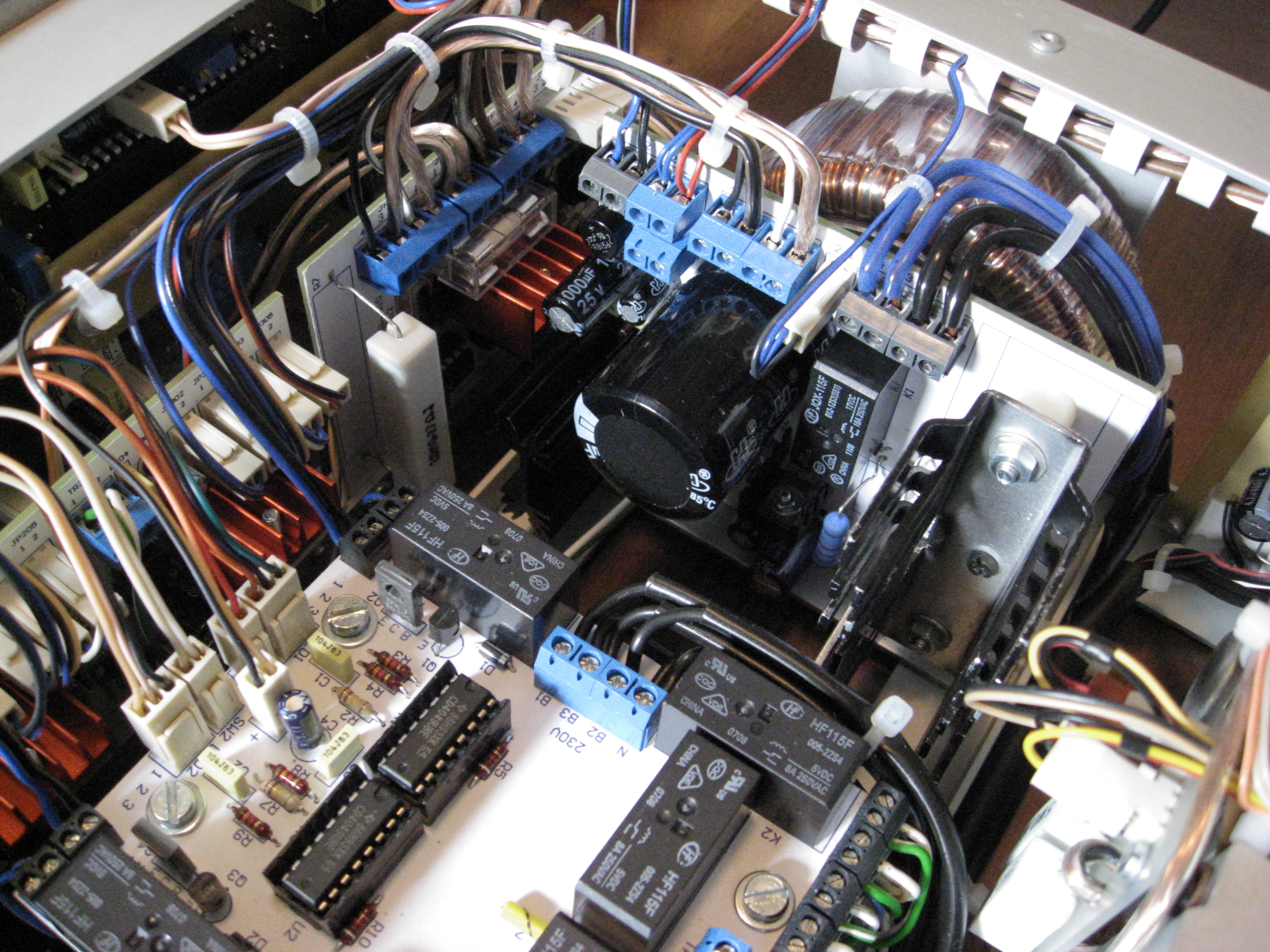
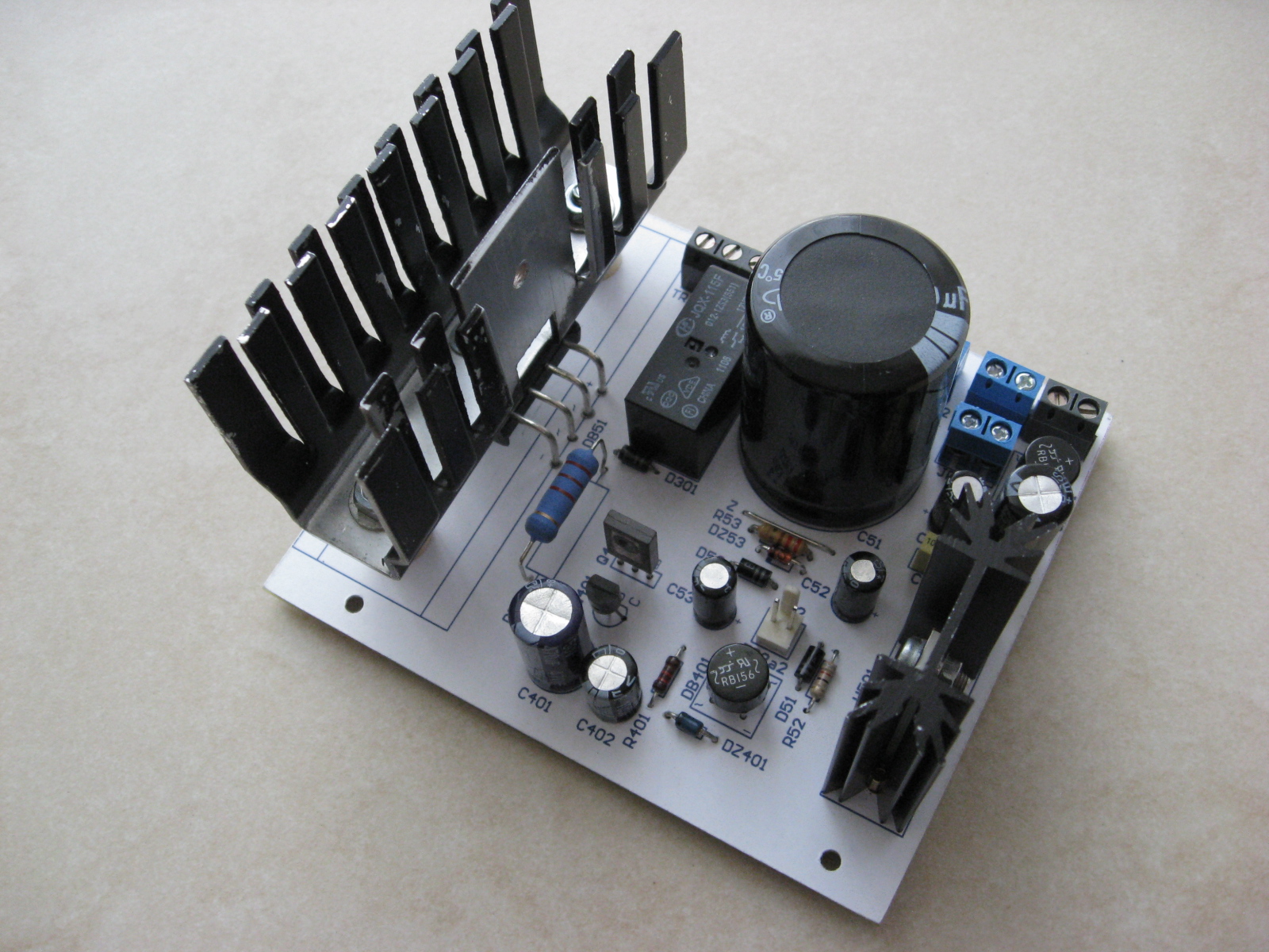
The first module “Z” is Greatz bridge, tension filtration, generation of negative tension to fund the operational amplifiers, 34VDC positive power fund for other operational amplifiers, fund from another auxiliary transformer for a relay to switch the main transformer steered form another board and a 5V 1A power supply to fund the measures.
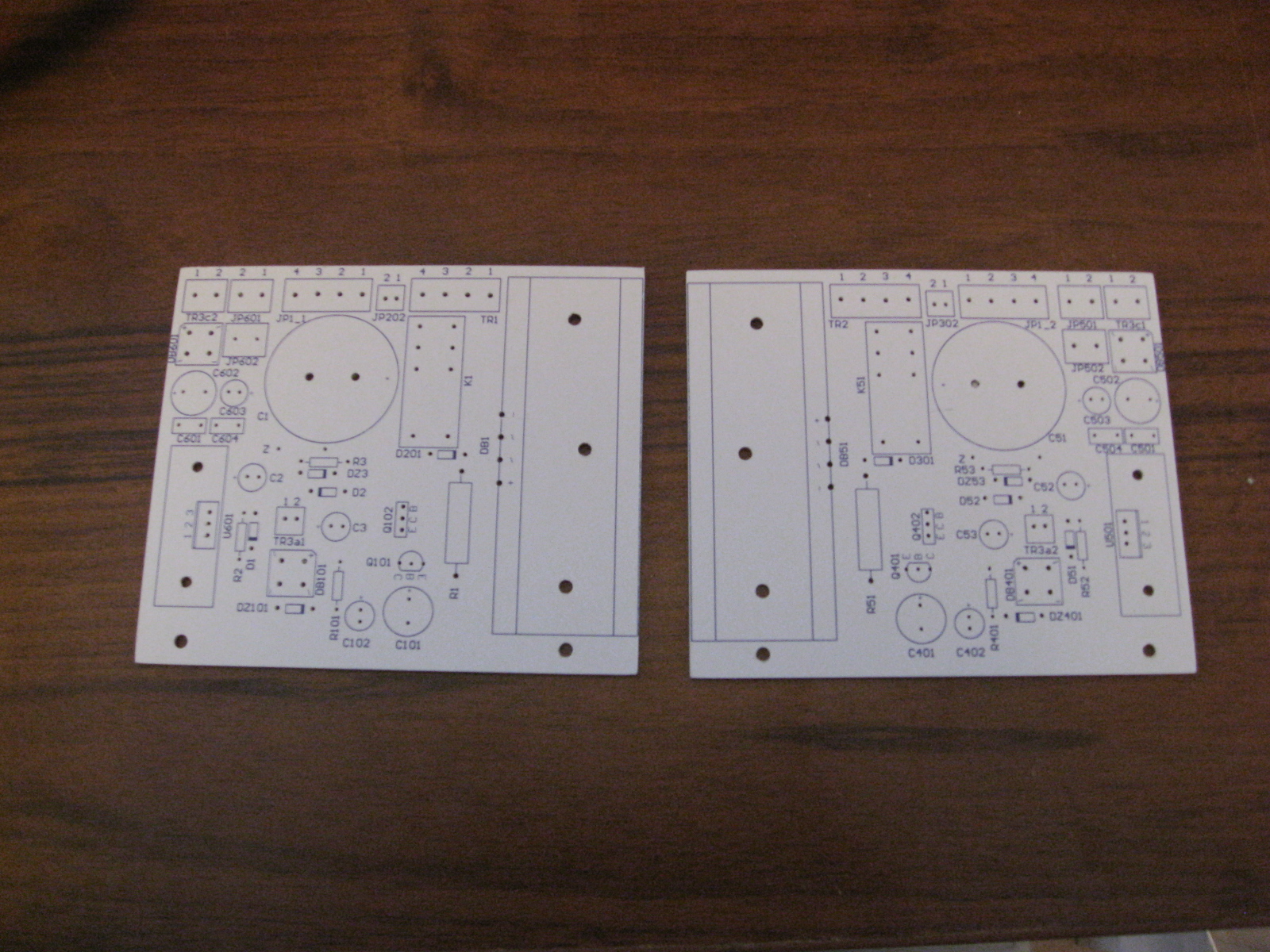
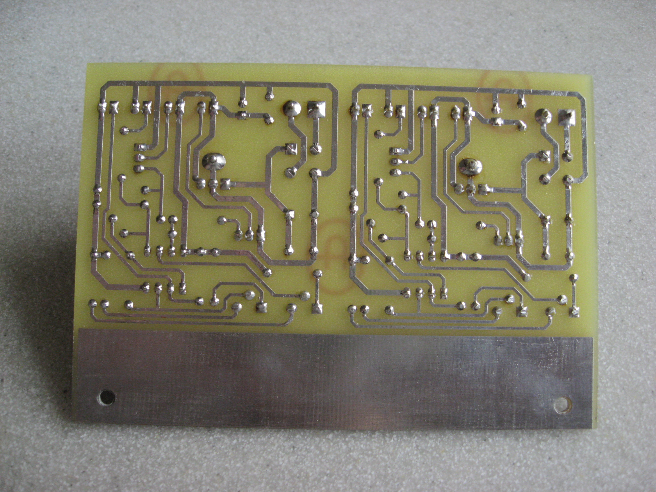
Both “Z” modules boards for power supplies are symmetrical to fit the housing. This helps to easily mount ARK connectors and the heat sink for the rectifier bridge.
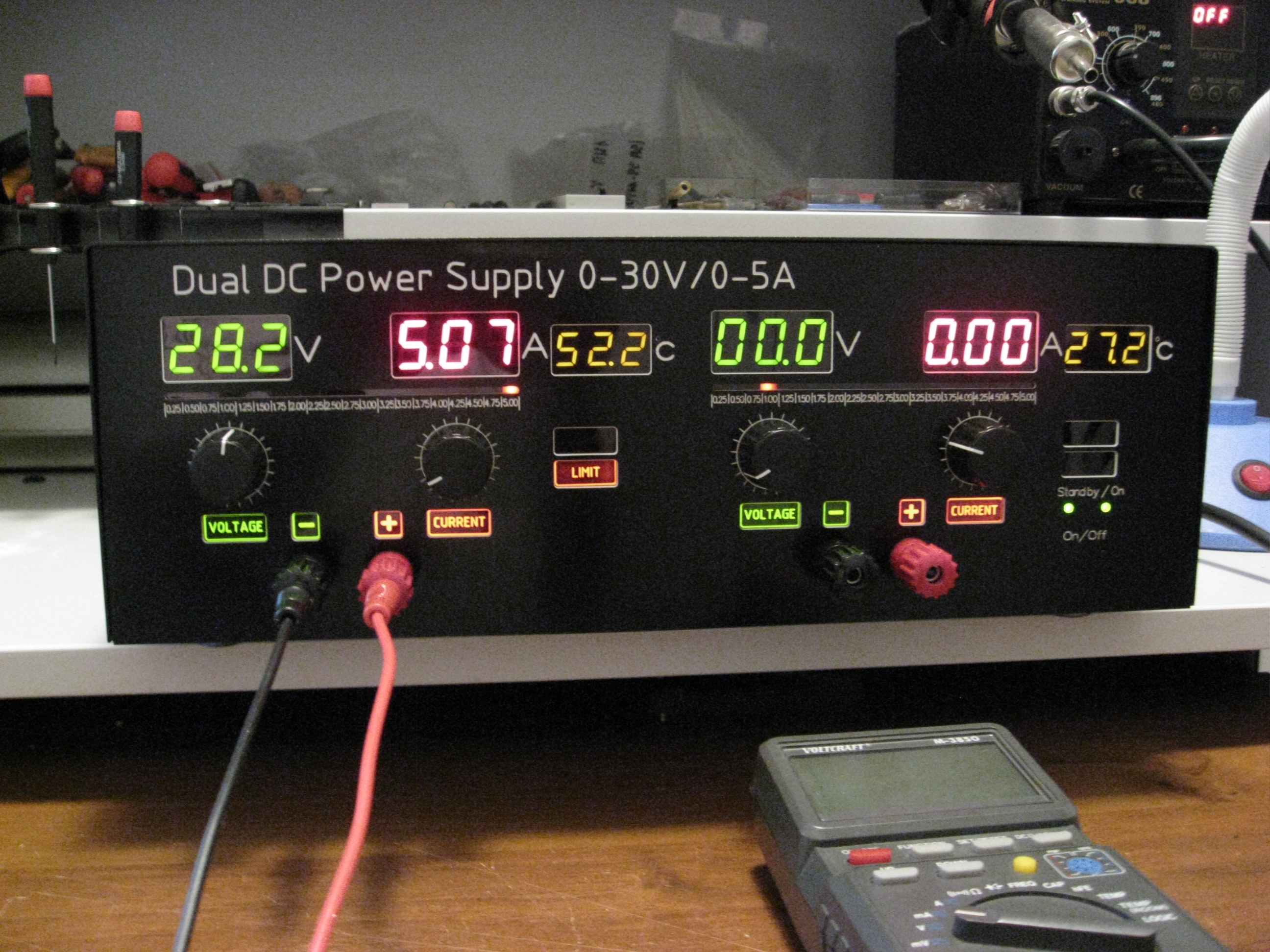
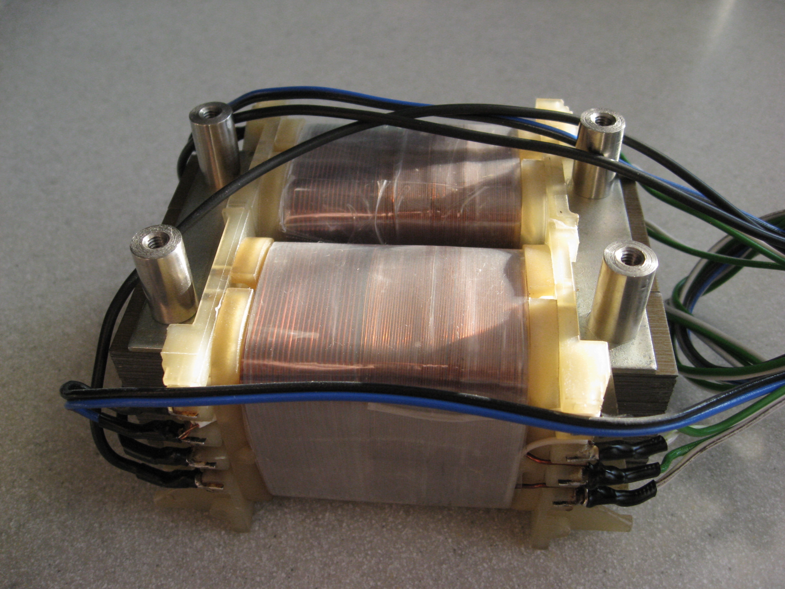
Main transformers have a double secondary winding, both 14VAC with current slightly over 5A. The power supply was build as a 30V but at this voltage it couldn't give 5A (on 28V it's ok). The filtering capacitor is 10mF.
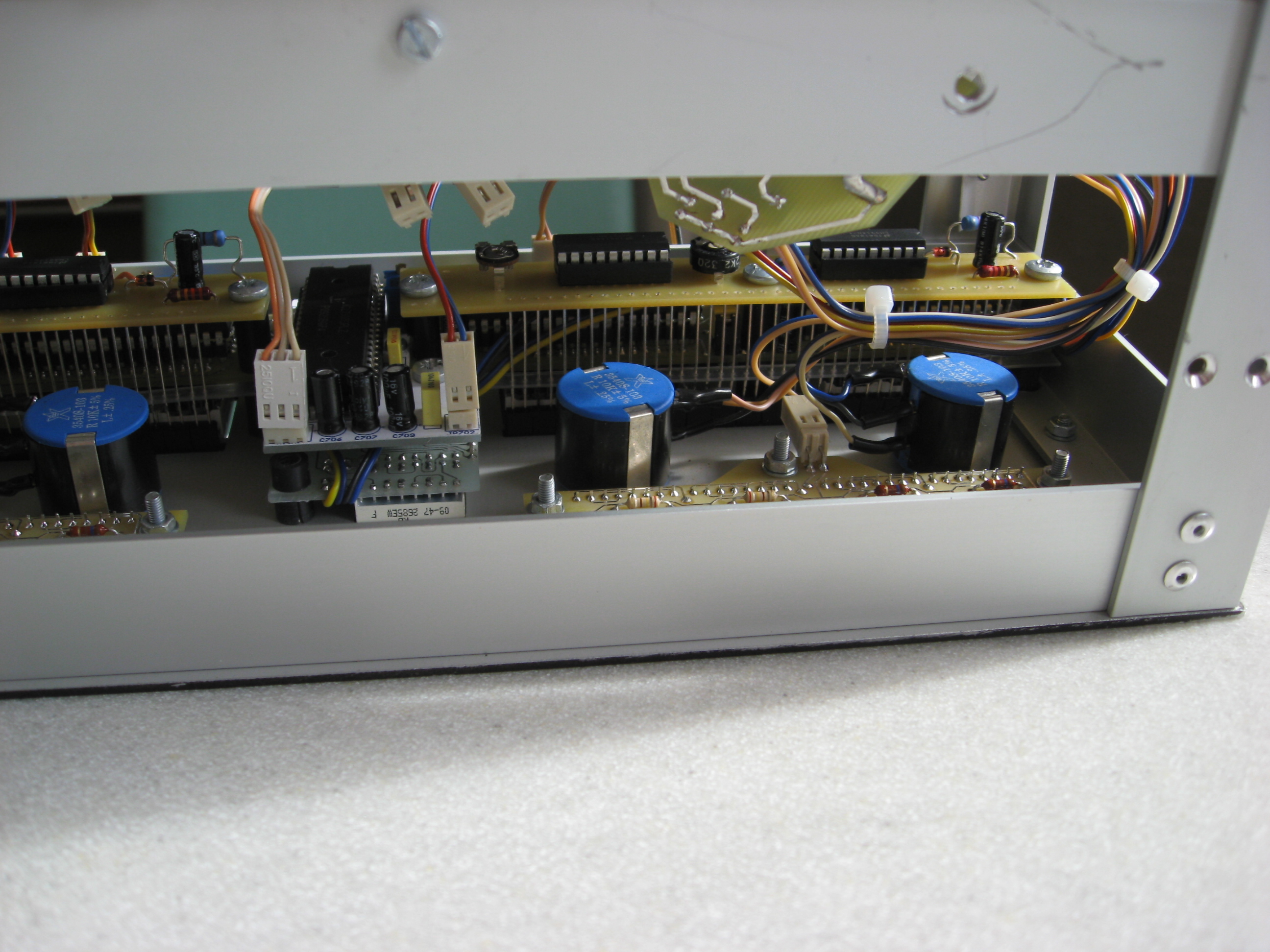
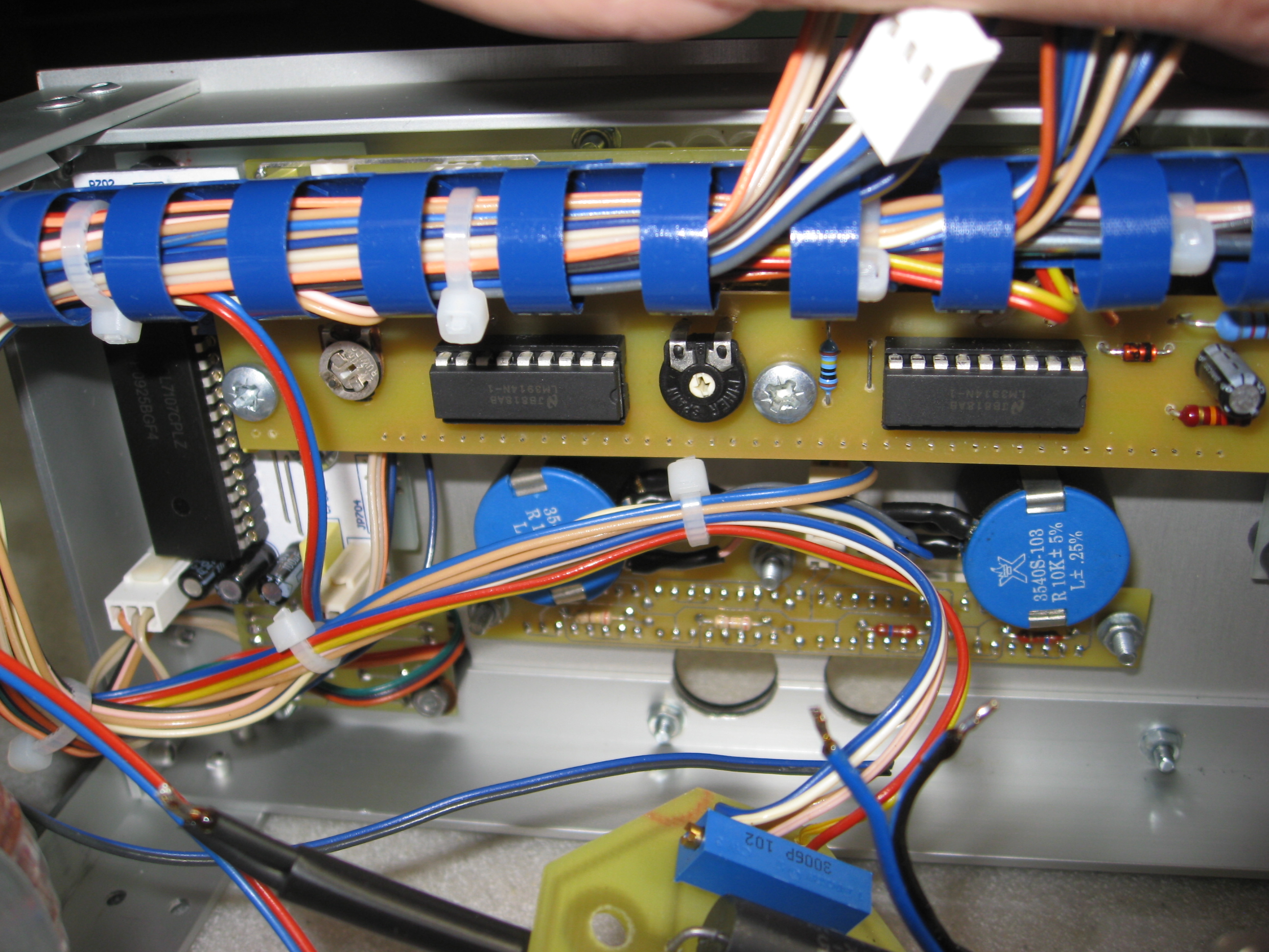
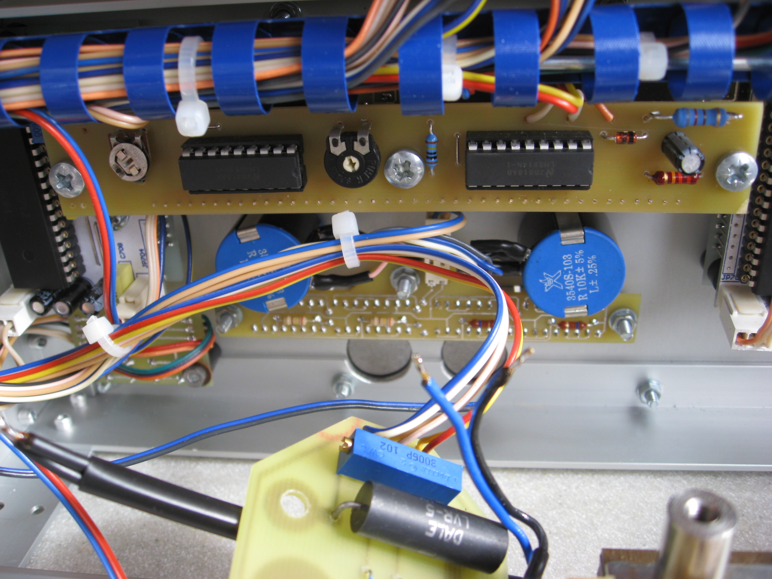
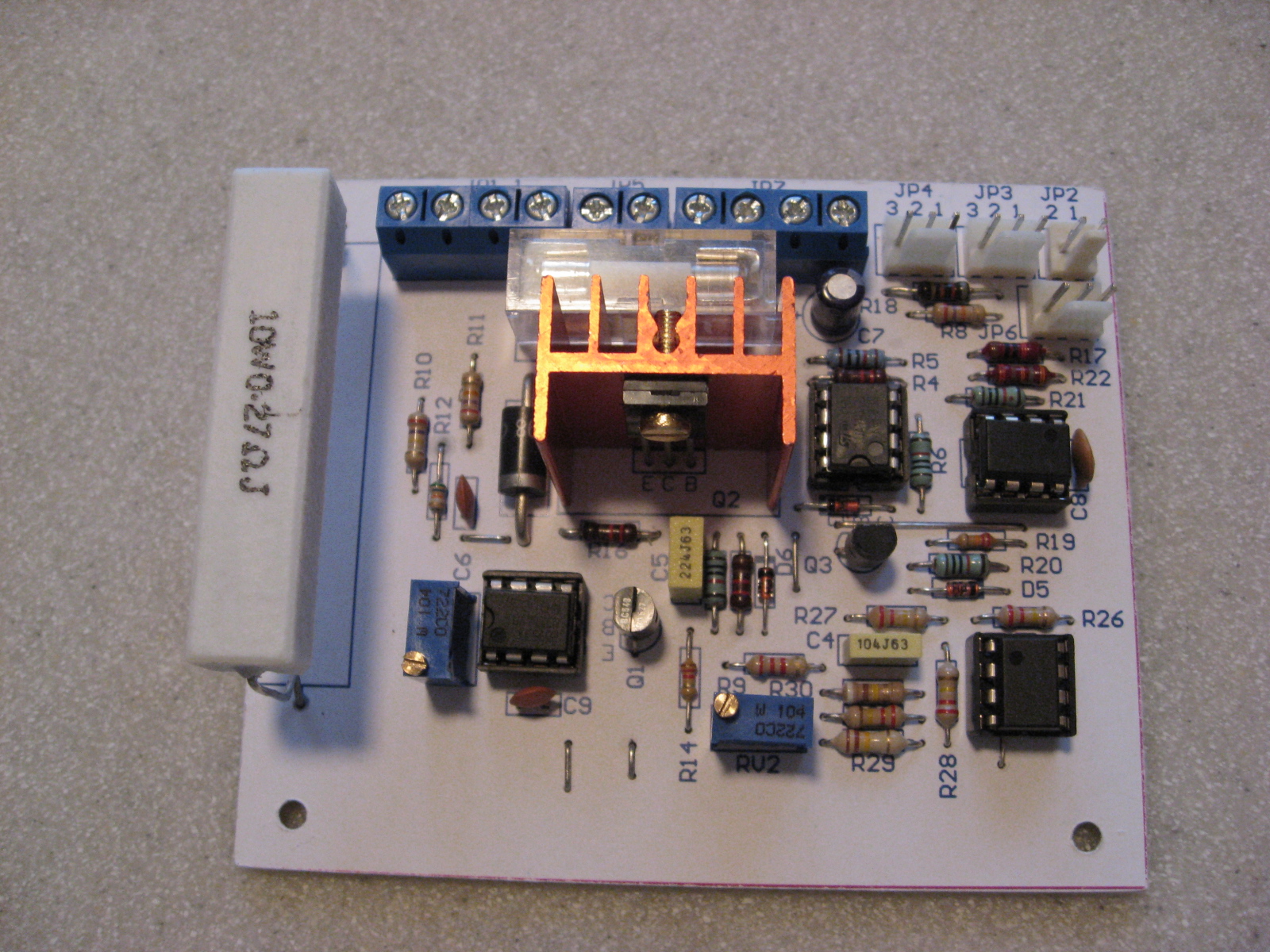
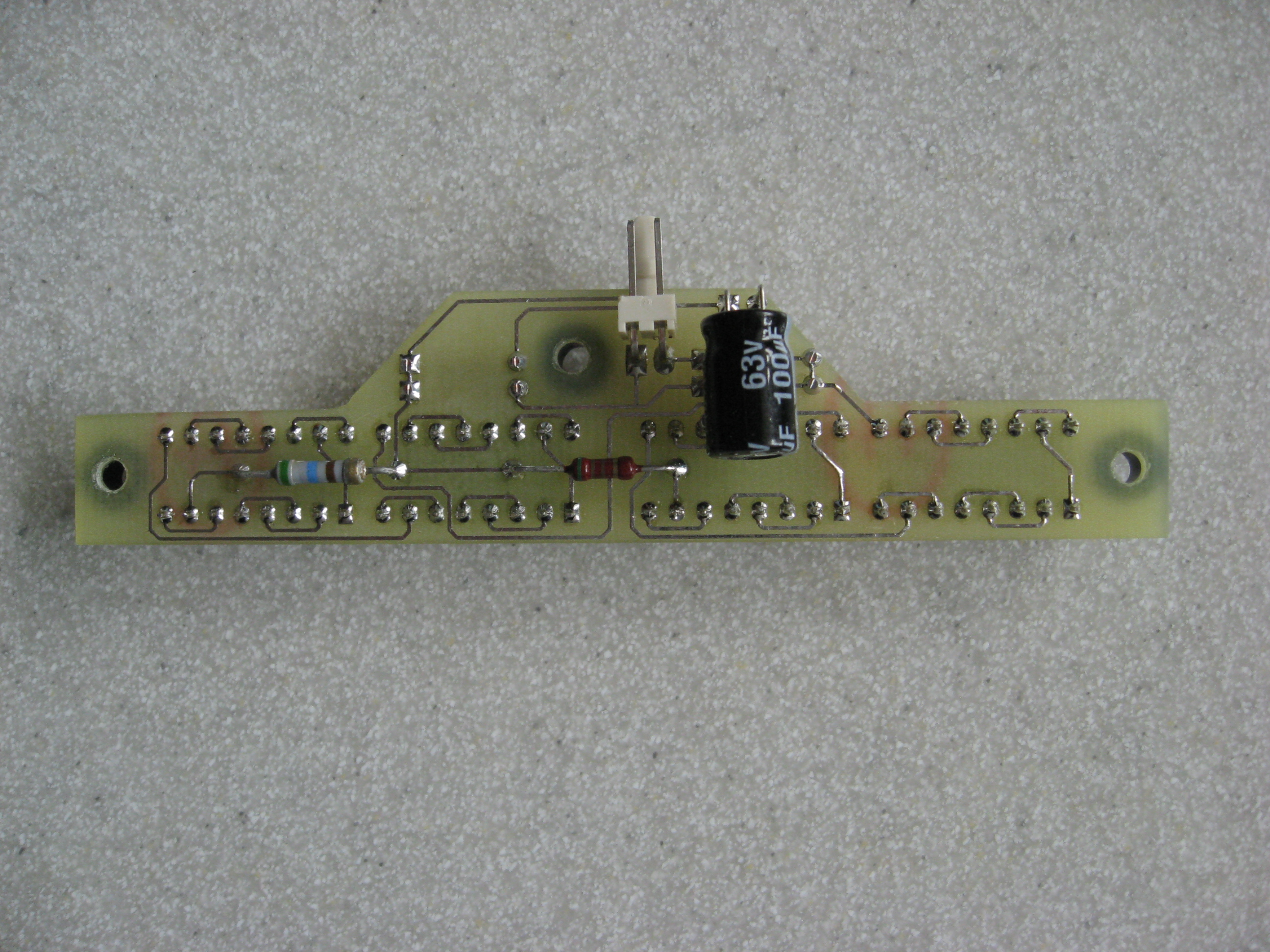
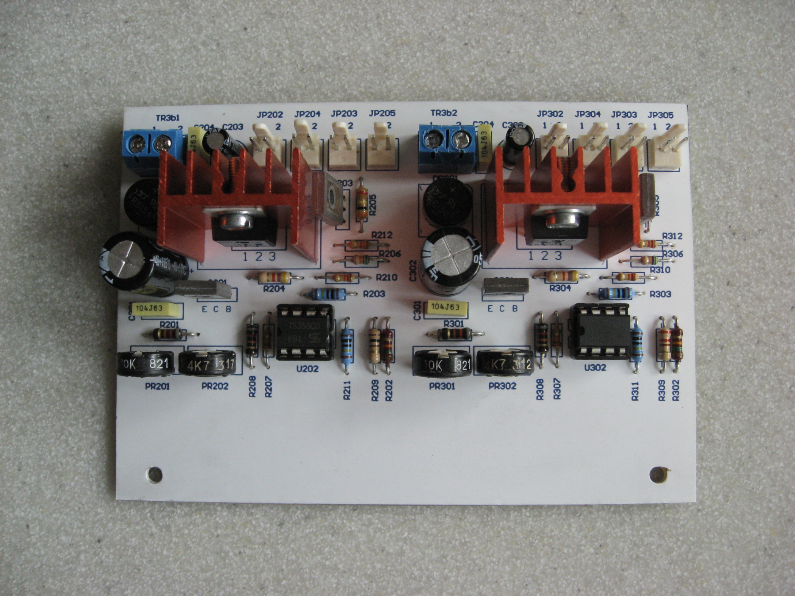
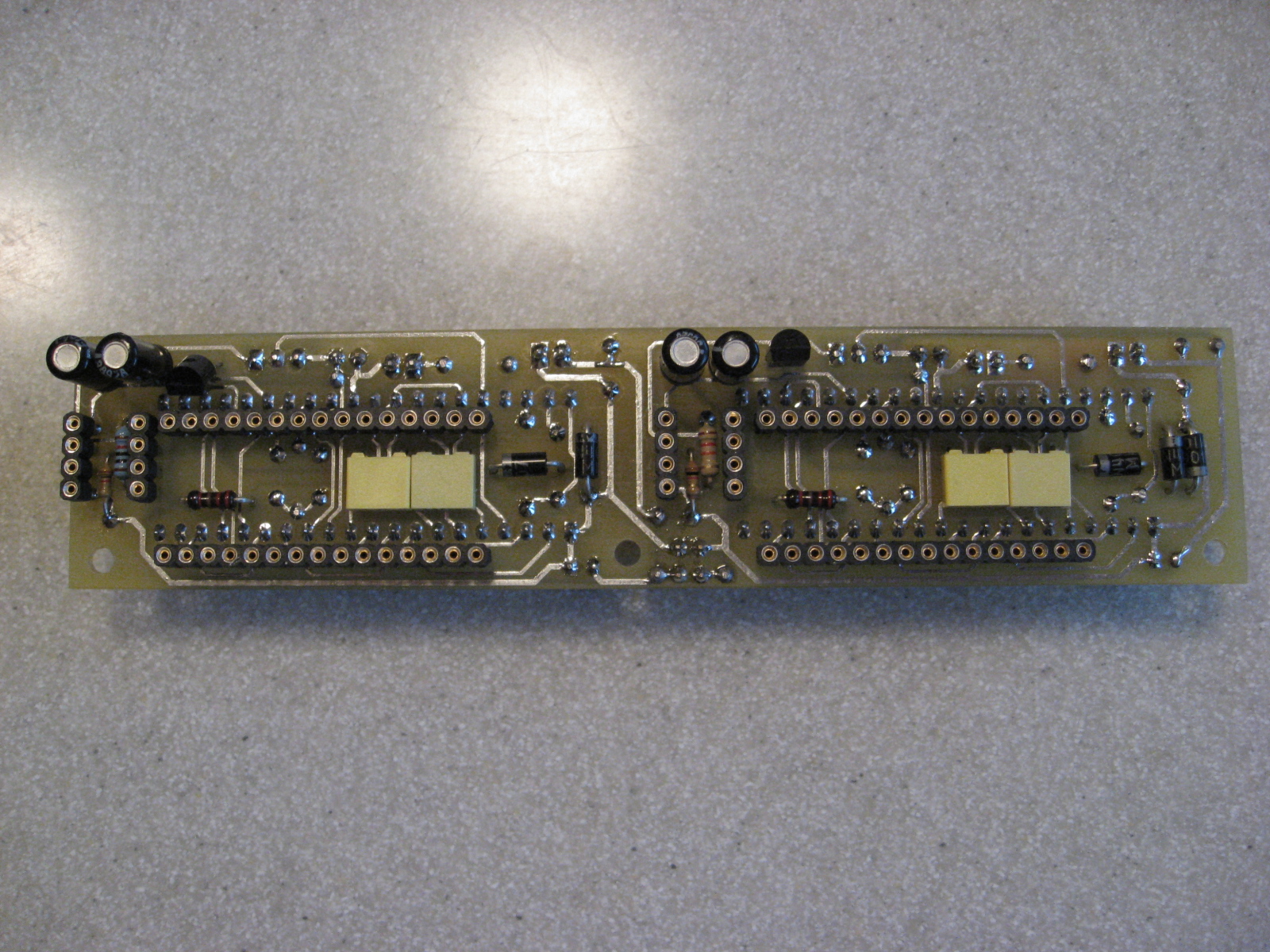
The secondary module is a version with additional operational amplifiers. The TL081 is used to generate power for the visualization system of the current limit set.
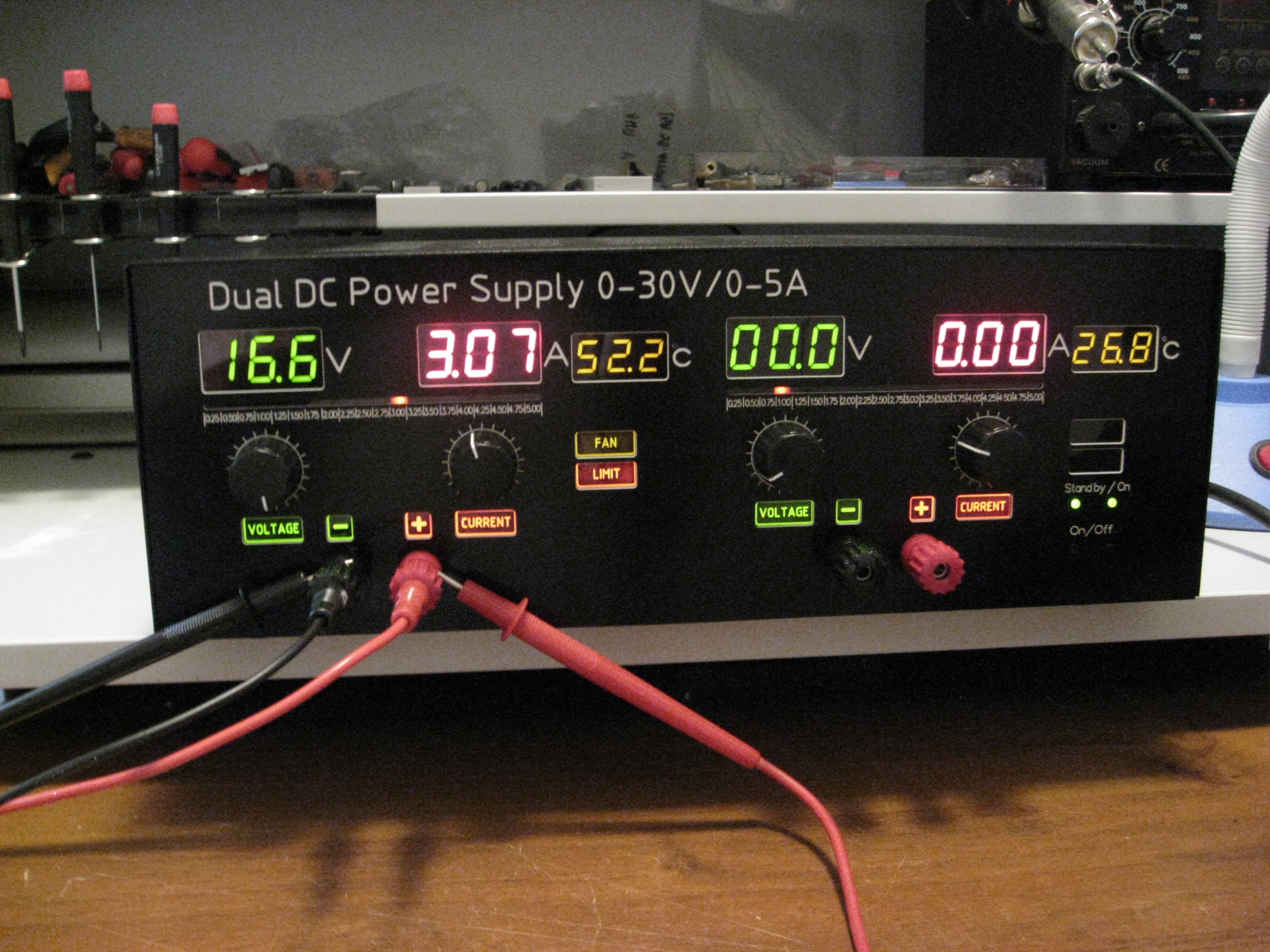
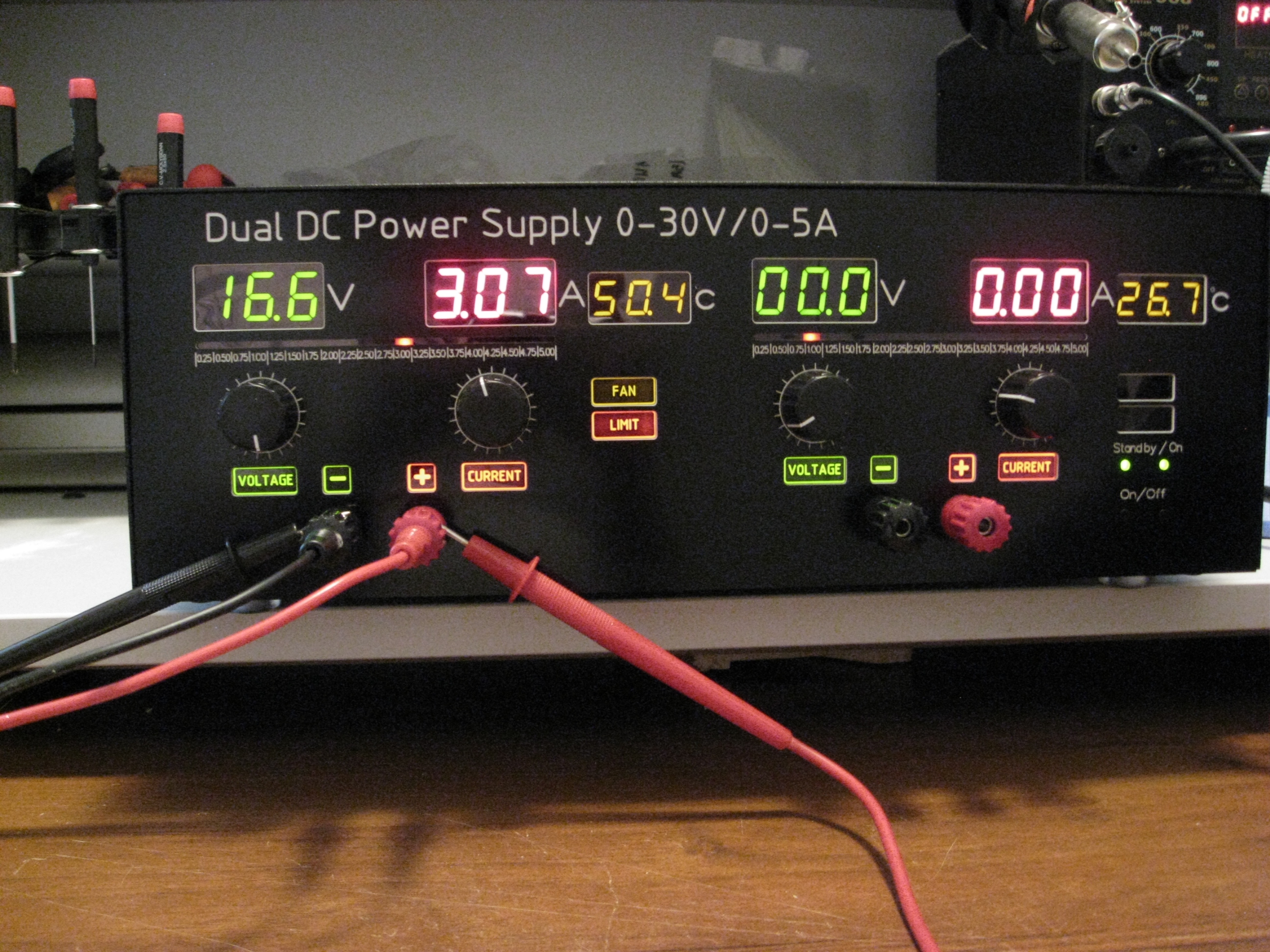
Depending on whether the power supply is loaded or idle, tension around the amplifier U3 responsible for current limiting, change (at the same setting on the potentiometer restrictions). The system compares voltage on the slider of potentiometer P2 to the voltage across the resistor R7. Part of this drop in voltage is supplied to inverting input U4. Thus, there is a voltage output adjustment potentiometer dependent, and almost independent of the load. On a scale from 0 to 5A, deviations are at 15mV, which in practice is enough to get a stable source to drive systems, which are popular LM 3914 LED line.
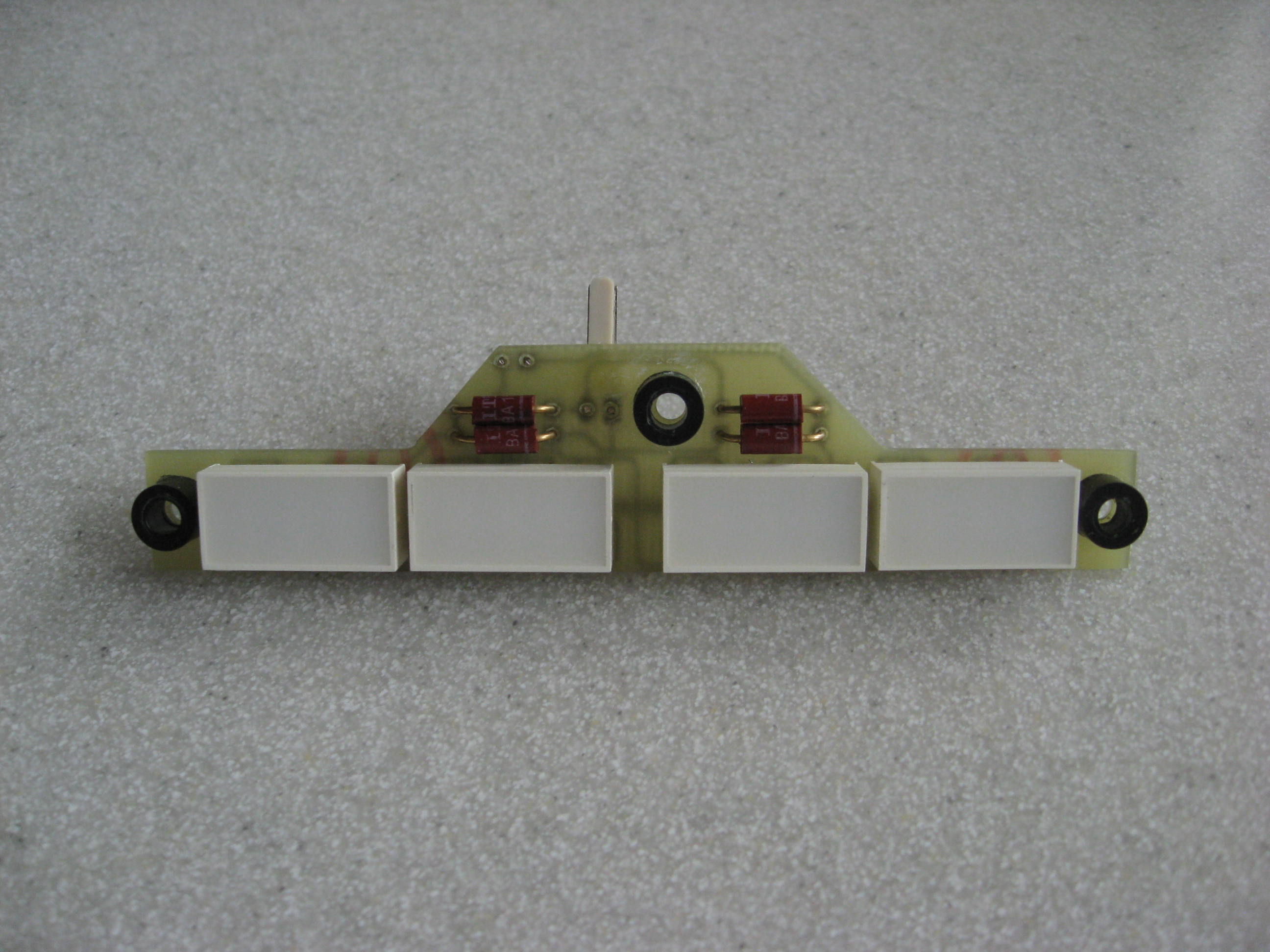
The visualization system is especially useful when multi-turn potentiometers were used in the control panel. This type of potentiometers allow easy voltage setting with an accuracy to three decimal places. Each LED in line corresponds to a value of 0,25A. This means that if the current limit is below 250mA, the line is off. The way of lighting could be changed from a moving point into the appropriate line, but it's better to choose the point – firstly, to avoid the effect of too much lighting points and secondly, to limit the current consumption.
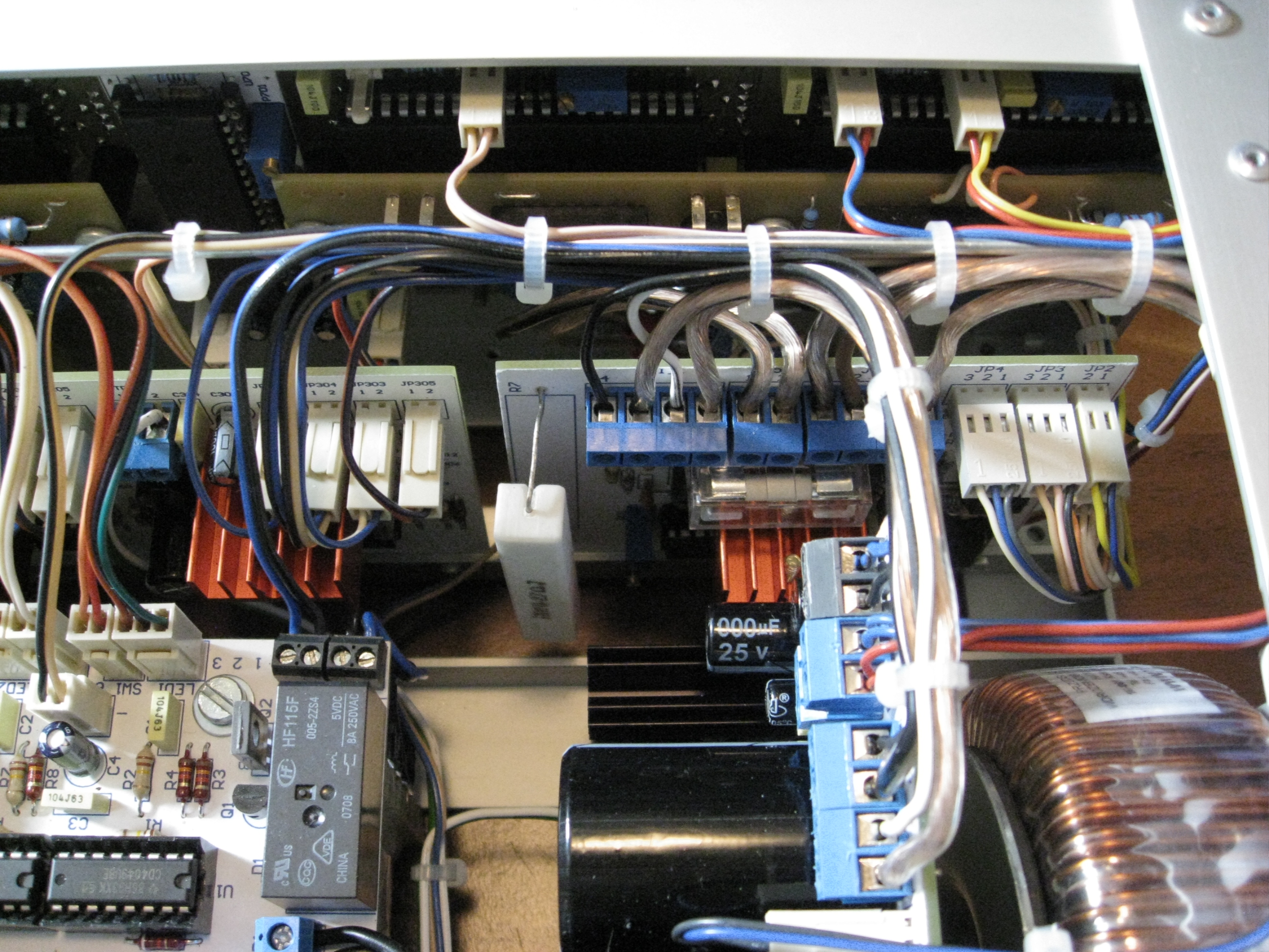
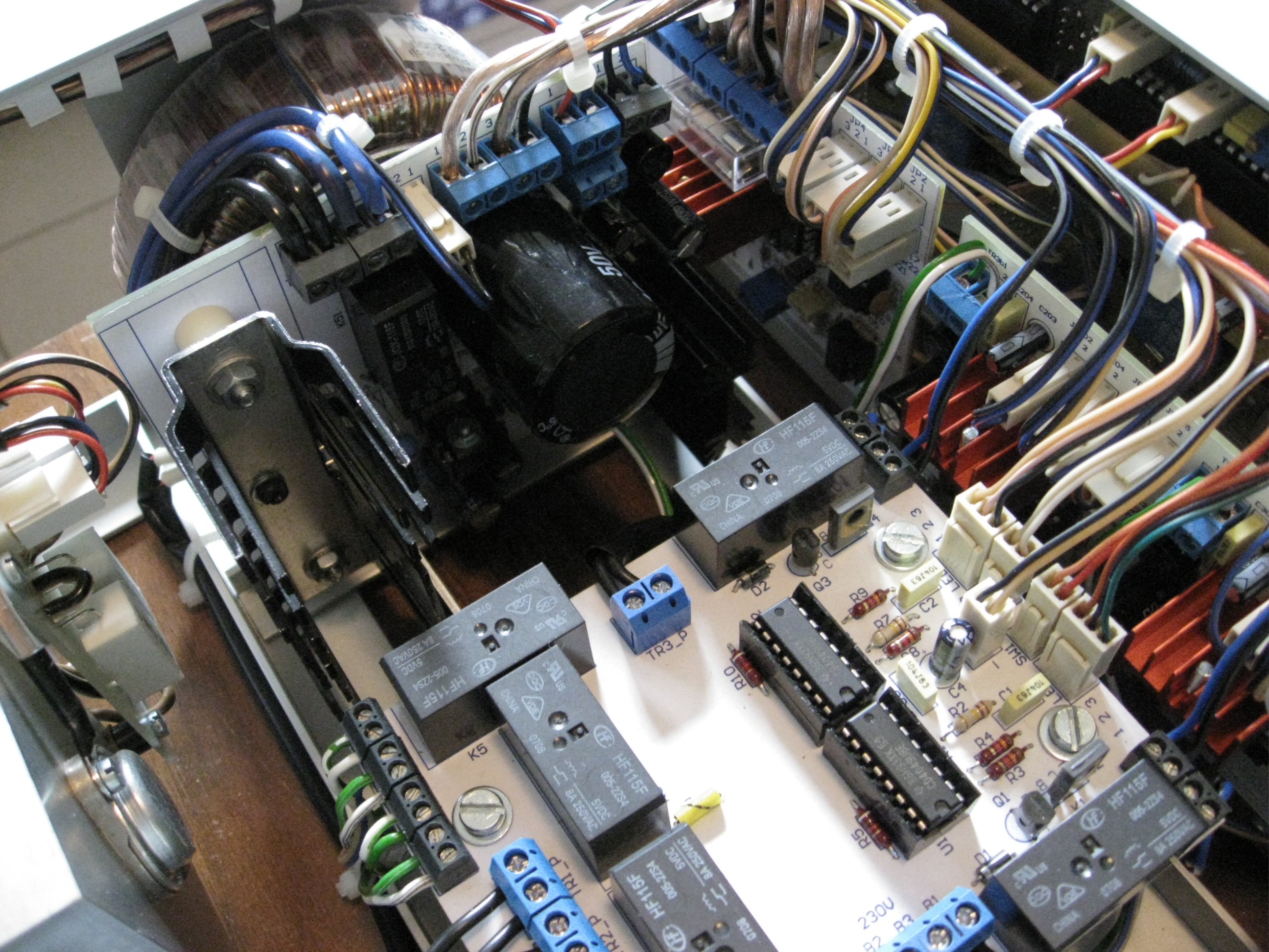
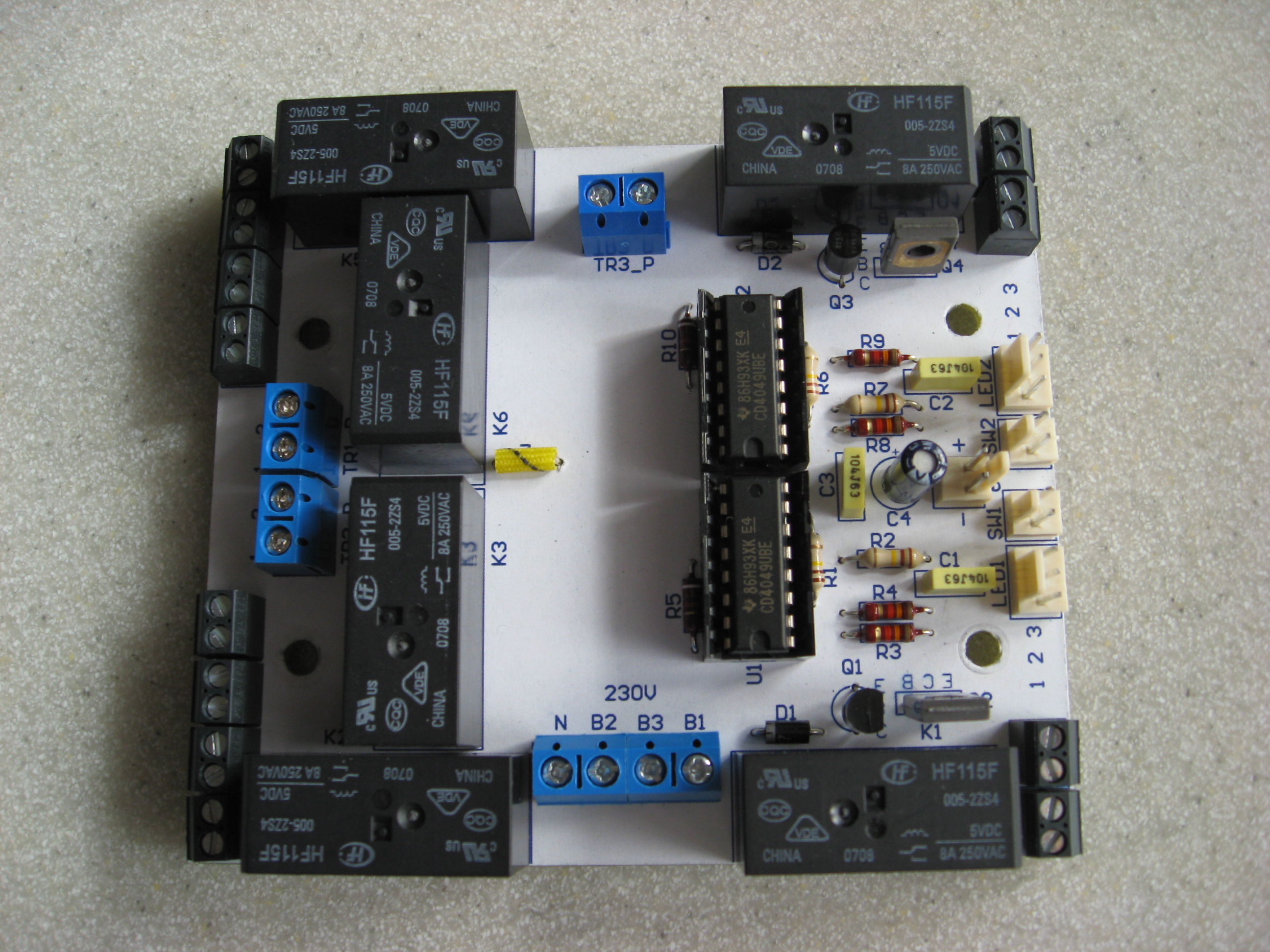
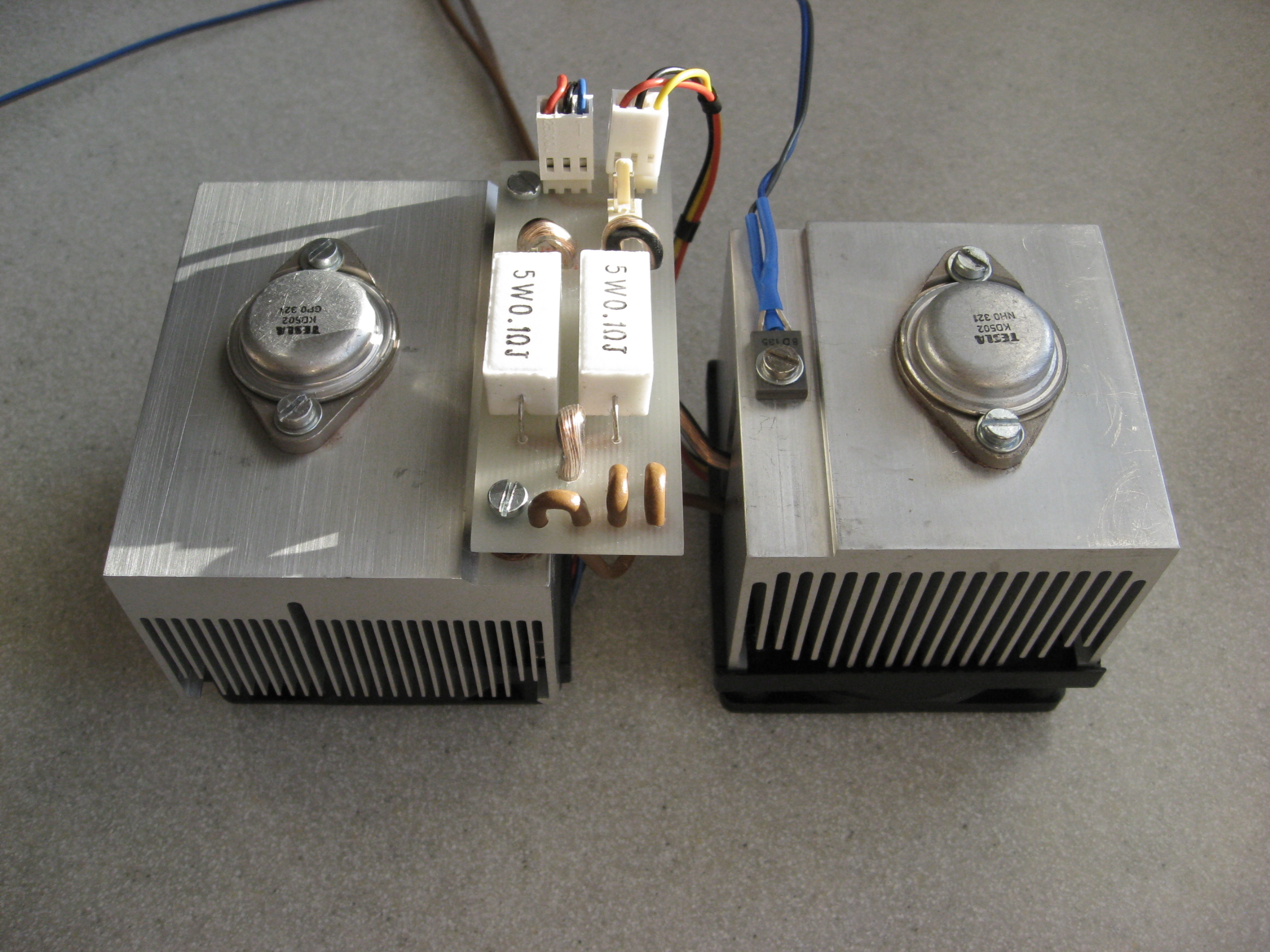
Another module is a system of switching the windings and fan control system mounted on the radiators coming from an old processor.
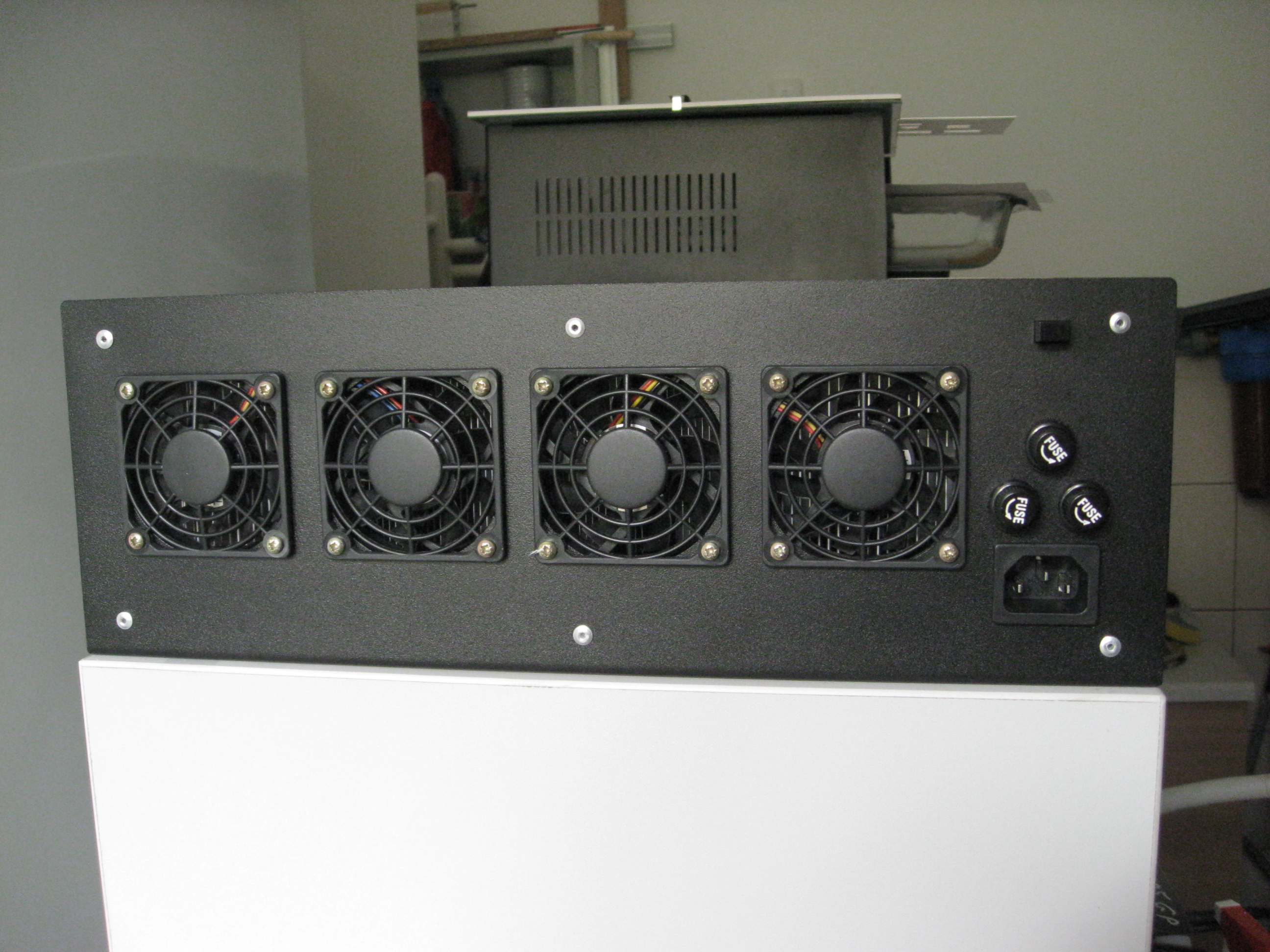
Power systems come from independent windings of the secondary transformer. LM358 chips which contain two operational amplifiers were used. As the temperature sensor, a BD135 transistor was used. After exceeding 55 Celsius degrees, the fans turn on. After cooling to about 50 Celsius degrees, they stop. Winding switching circuit is responsive to the voltage taken directly from the output terminals and power supply has a hysteresis of about 3V, so there is no occurrence of too often relay work.
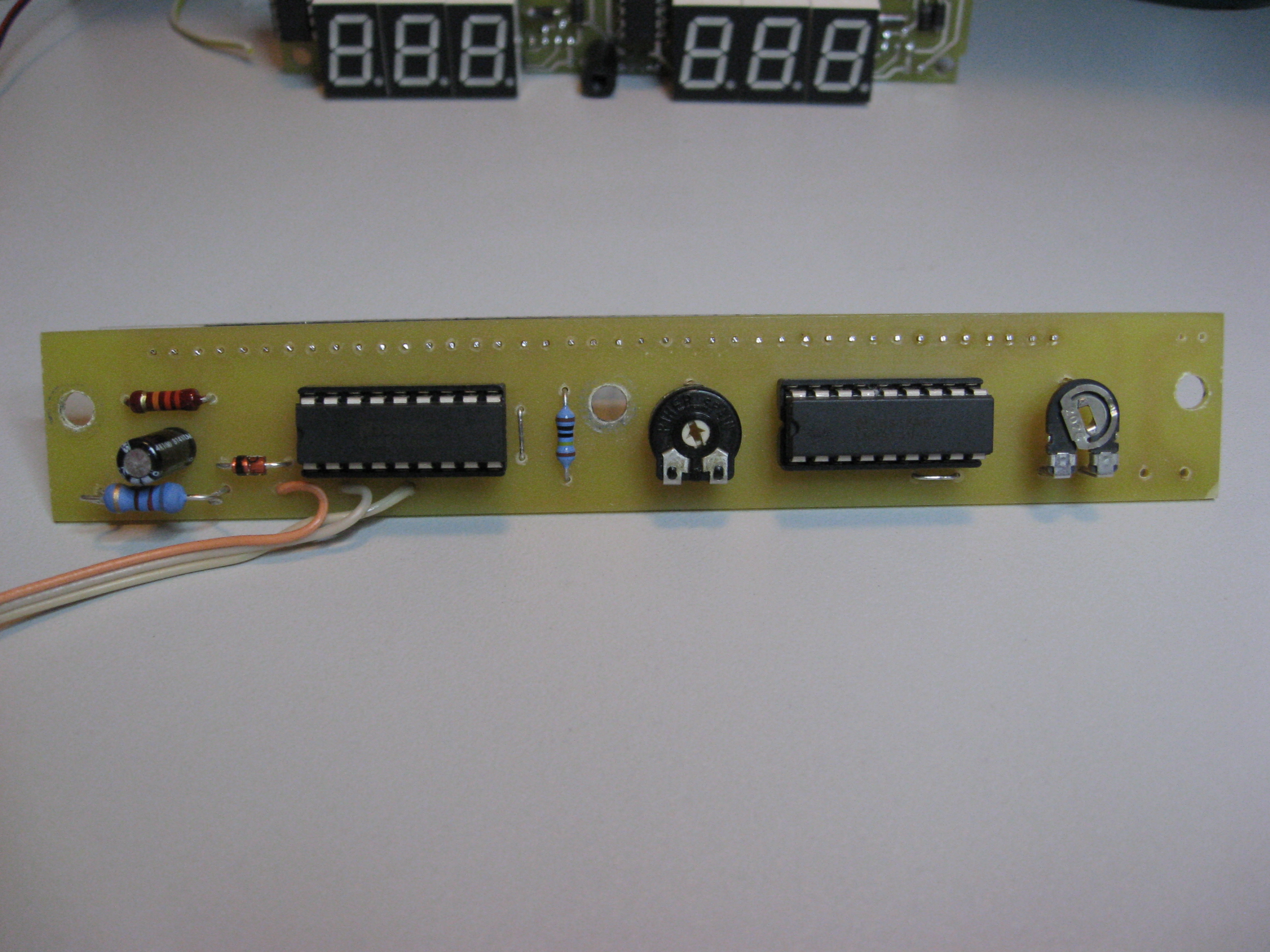
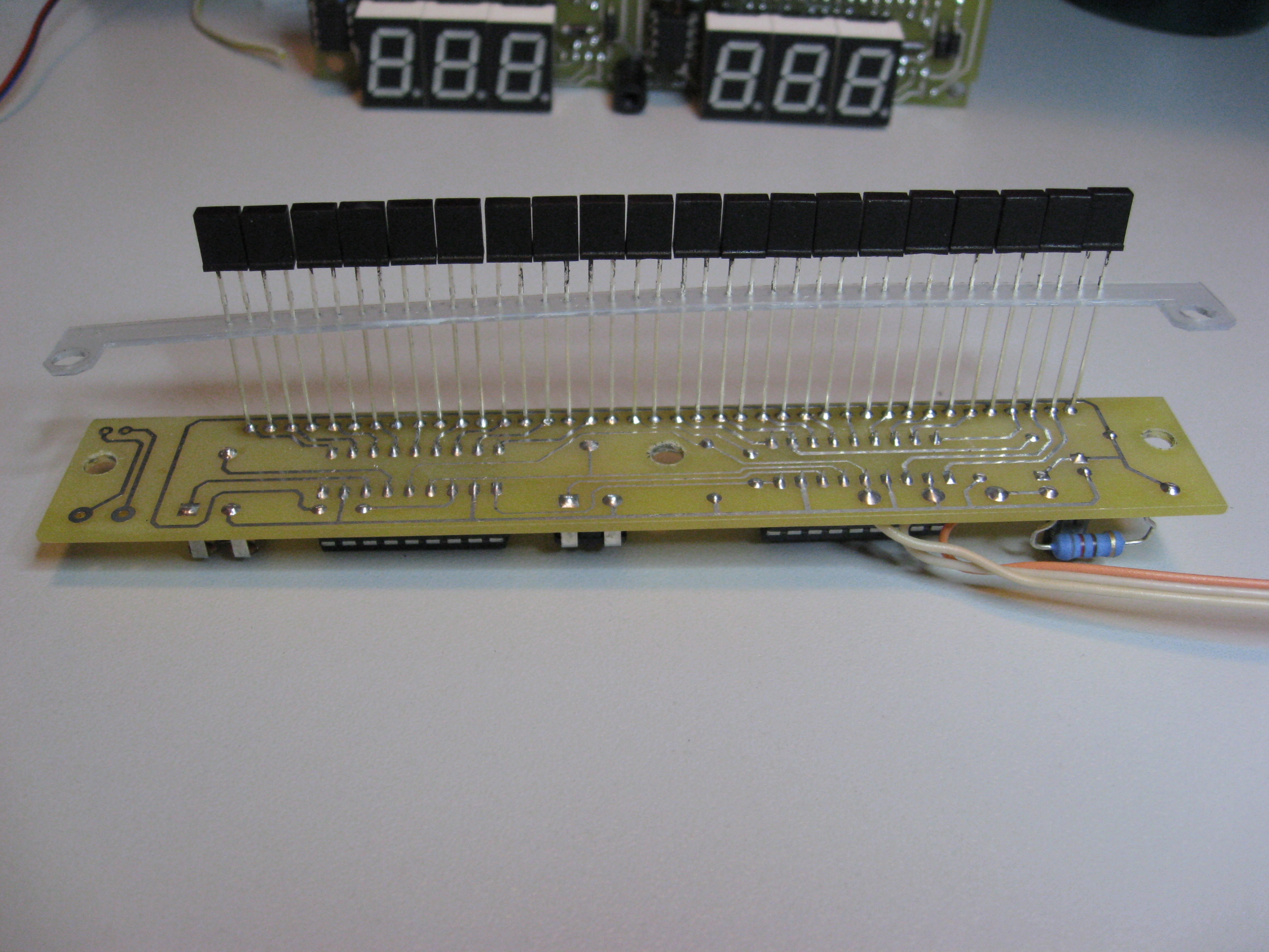
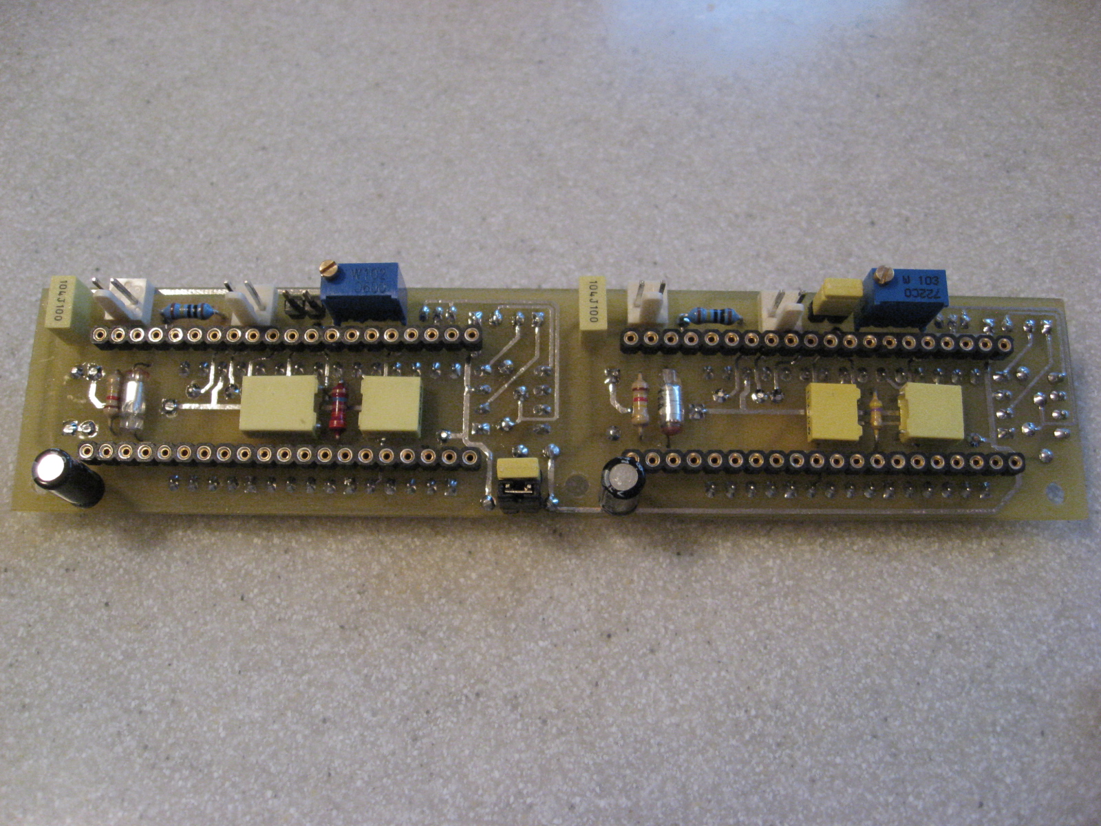
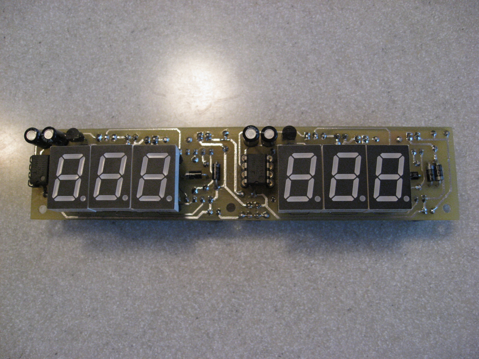
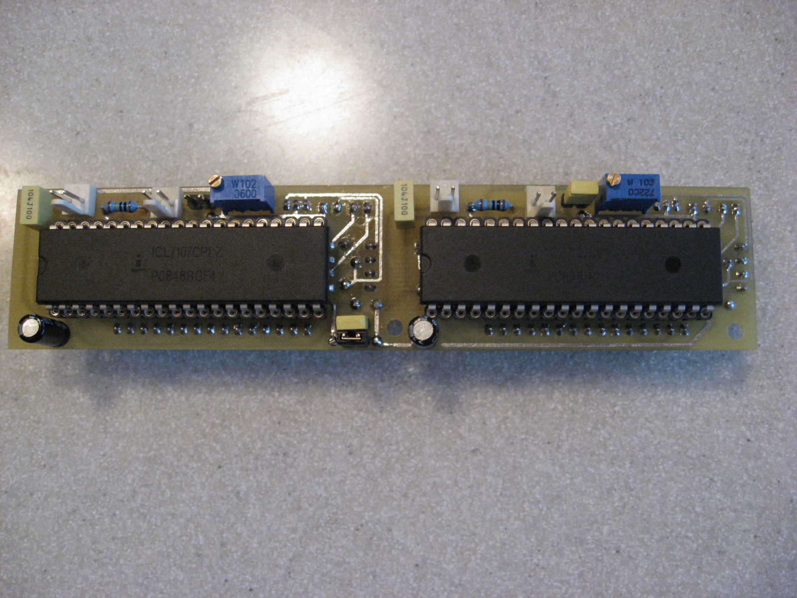
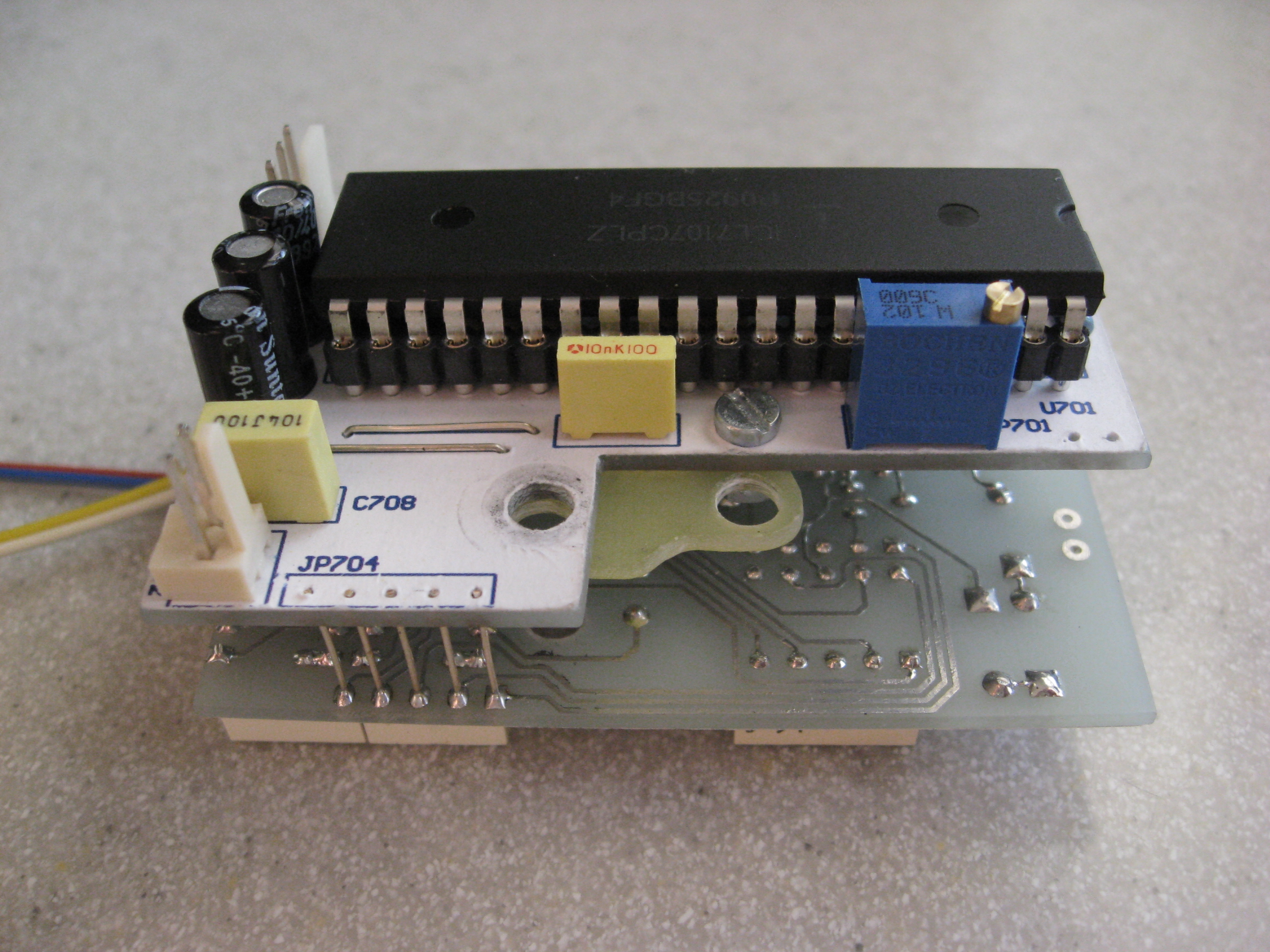
Measurement of voltage and load current is based on the ICL7107 dice. The measures' plates are bilateral and designed so that for each adapter on one plate is a voltmeter and ammeter. Also, there are measures of the radiators' temperature. It was done by using the ICL7107 dice and LM35 as a sensor.
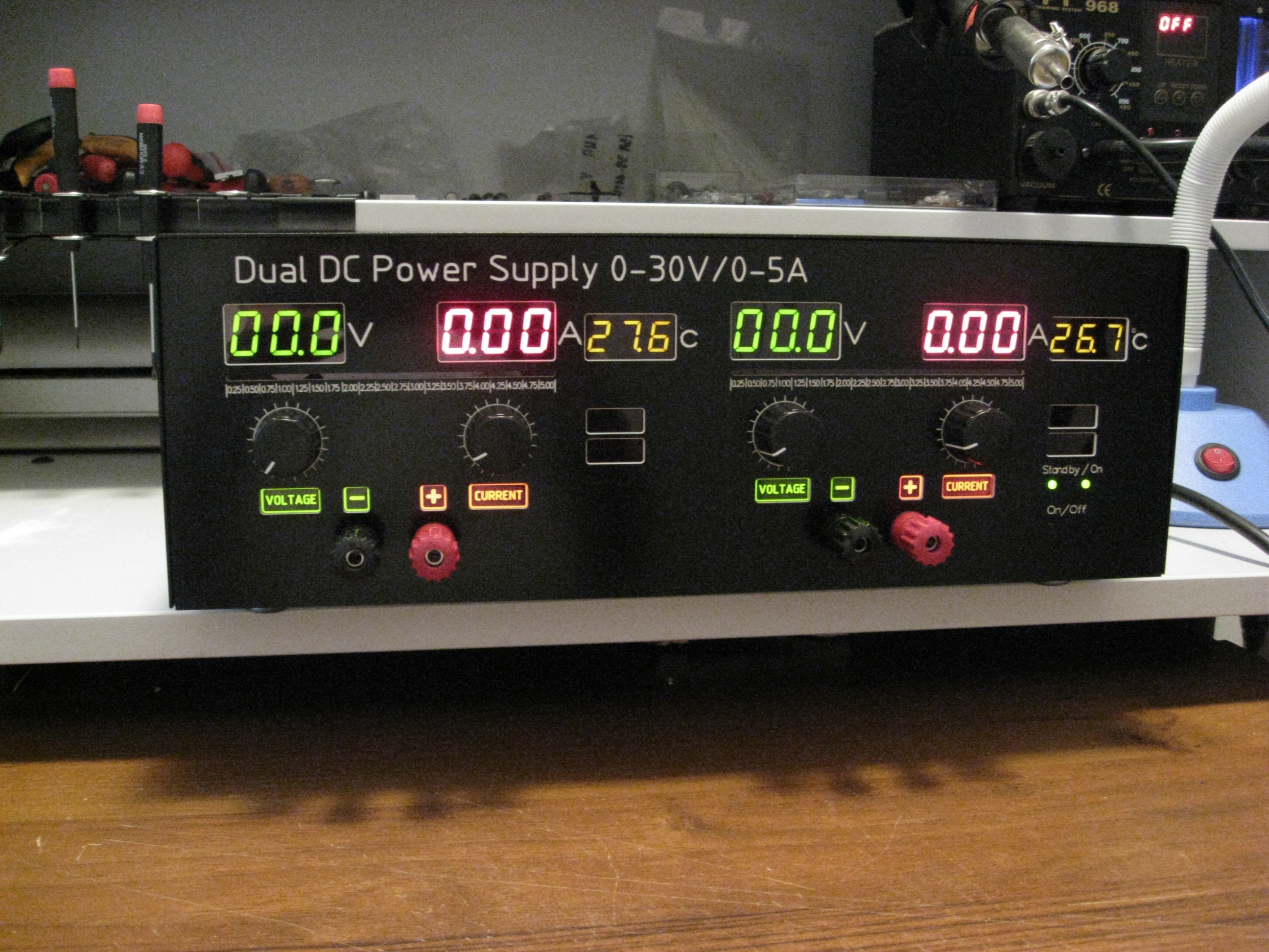
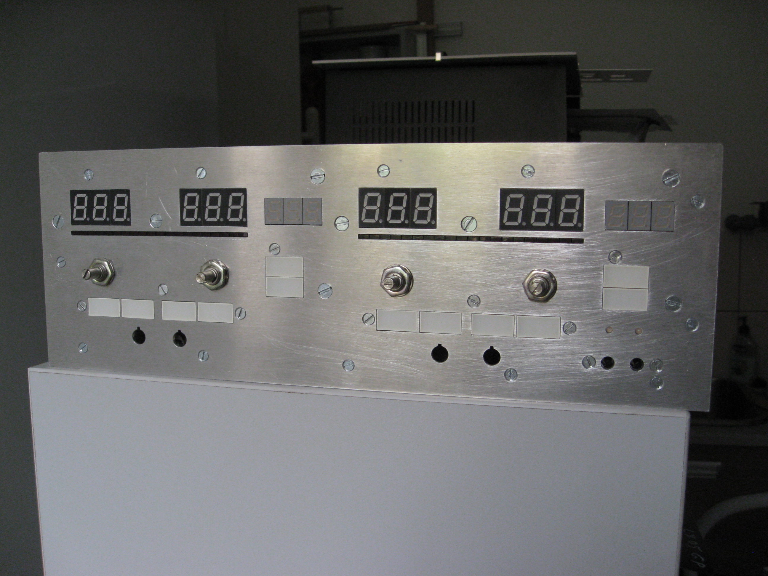
The visualization of power parameters is viewed on seven segments displays, because they are easier to read than standard LCD display.
All auxiliary systems are powered by the transformer, which was rewound removing all the windings outside the original network. For this purpose TS90/11 was used. As a secondary ones, 2x26VAC were rewound to power the operational amplifiers, 2x8VAC to power the meters and 2x13VAC to power supply switching circuit windings and the temperature control system. In total, six independent windings were formed.
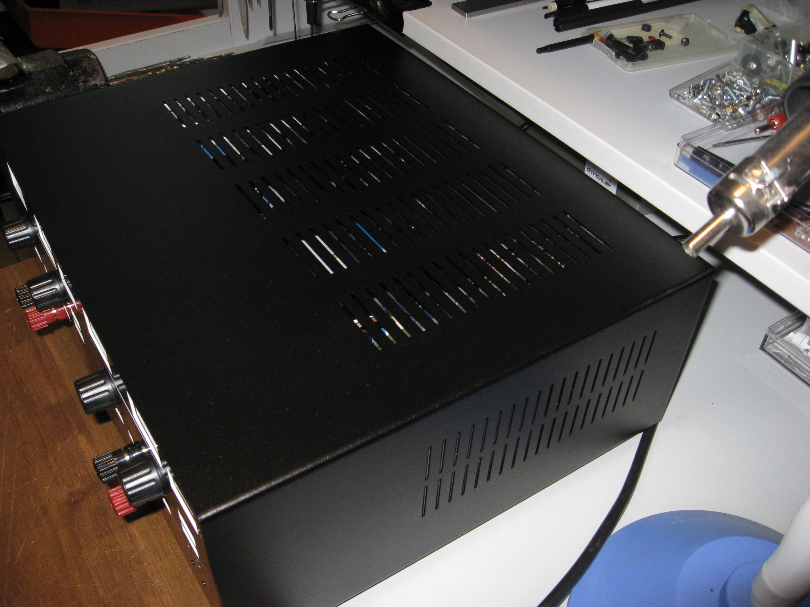
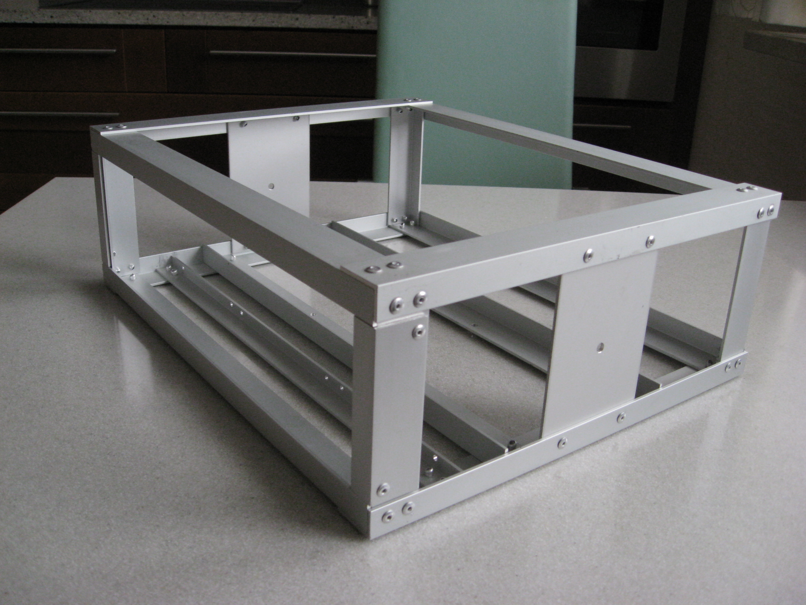
The whole device was placed in a housing, which was made to order, because it isn't easy to make it yourself. An aluminum frame could be made at home. Aluminum front panel, which serves as the mounting of all gauges and additional elements could be done on milling machine.
The following sequence:
- making the module with the rectifier bridge, filtering and relay, connection to the transformer and activation of the relay from an independent source to verify the output voltage.
- making the module of windings switching and cooling radiators control. Running this module would facilitate the adjustment of the proper power supply. To do this, another power supply is needed to provide regulated voltage at the input circuit responsible for control relay. The temperature system can be started by simulating the temperature. For this purpose, the heat gun was used to gently heat up the radiator and the BD135 sensor. Temperature was measured by a sensor attached as an multimeter equipment. In both cases, the adjustment is to align PR201 and PR202 or PR301 and PR302, respectively.
- then the proper power supply should be started and then RV1 regulated to reach 0V at the output. It would be helpful to control the current limit. The limit itself depends on R18, R7 and R17 resistors value.
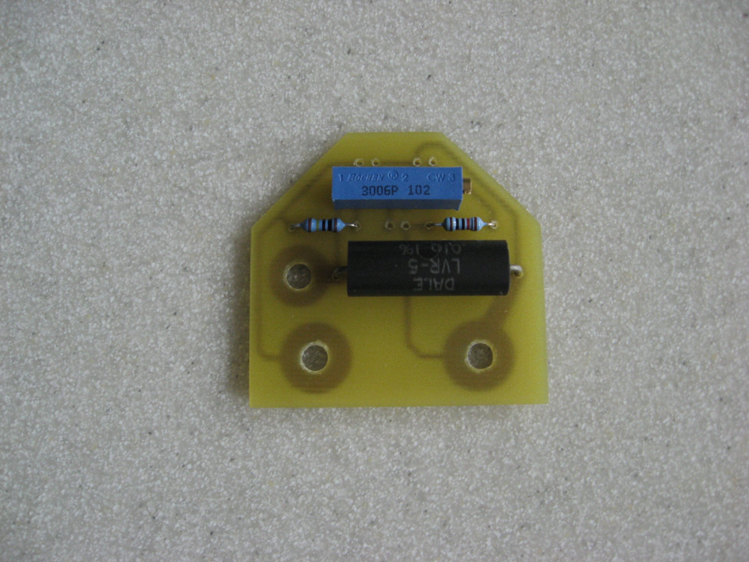
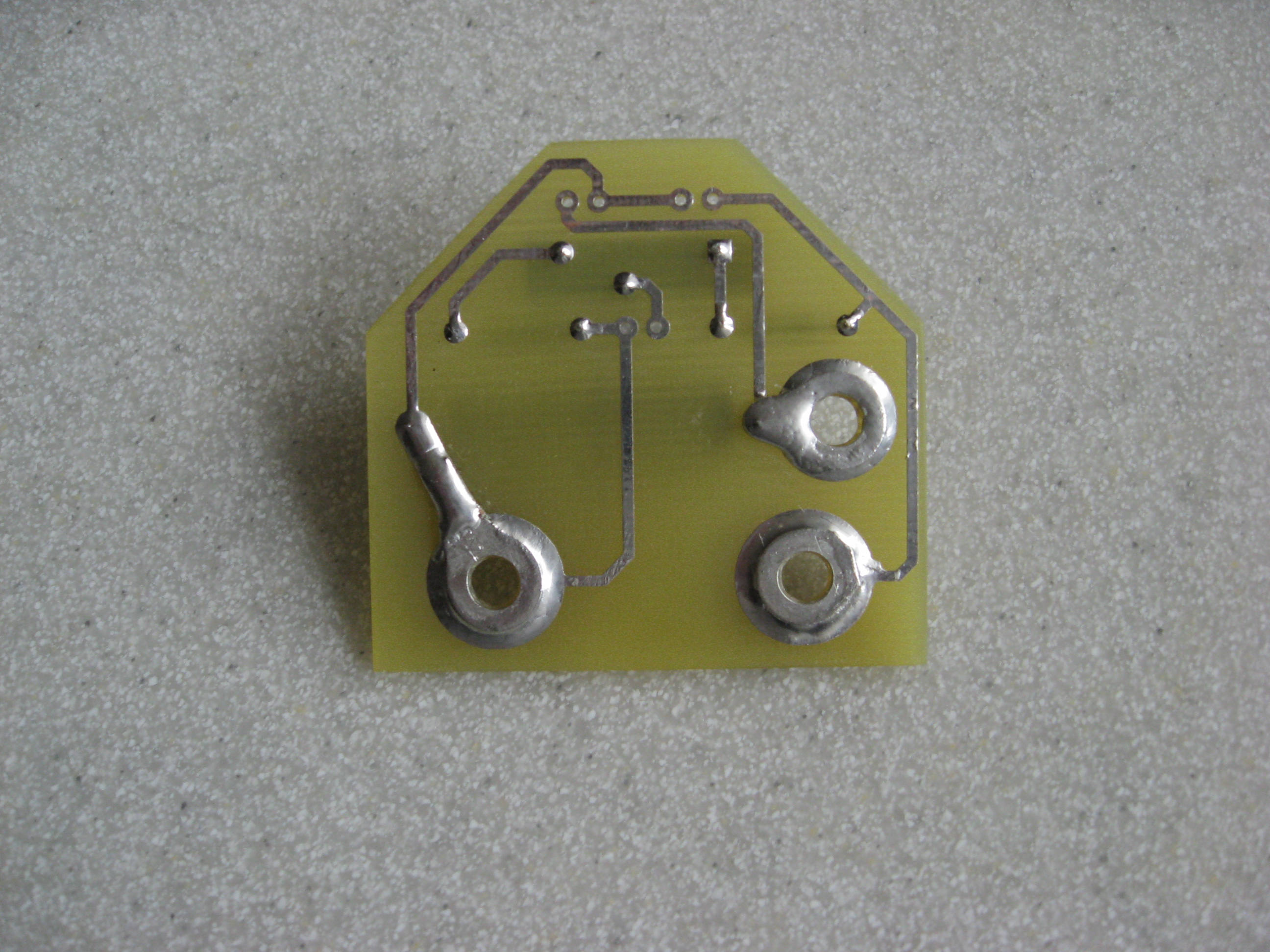
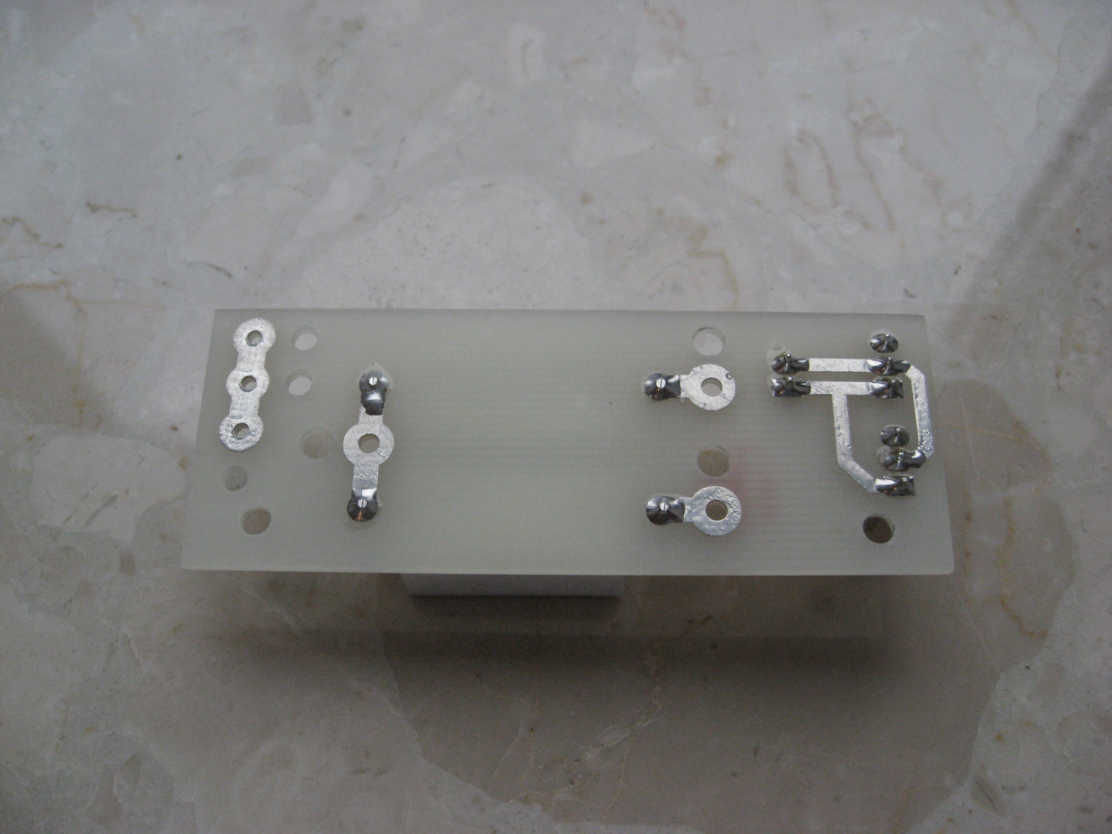
Directly at the output terminals, the plate with voltage divider to a voltmeter with a resistor 0.01 Om/5W was mounted. There the voltage drop is used to measure the load current.
An additional element of the power is the circuit that allows switching only one power supply without the need for a second one, even though the auxiliary transformer supplies both power supplies. The system on and off control was placed on the same plate. It works by one low-current button for each power supply.
The system is powered from the inverter, which in 'stand by' state takes about 1mA from 230V. In fact, idle state in this sense does not occur, because even then it's signaling the state with double-color LED. Whether the method of controlling a device, a typical switch completely isolating the device from the network is mounted on the back.
Plates were made by photochemical method (Positiv20). Descriptions of elements on plates are made on stickers.


 **broken link removed**
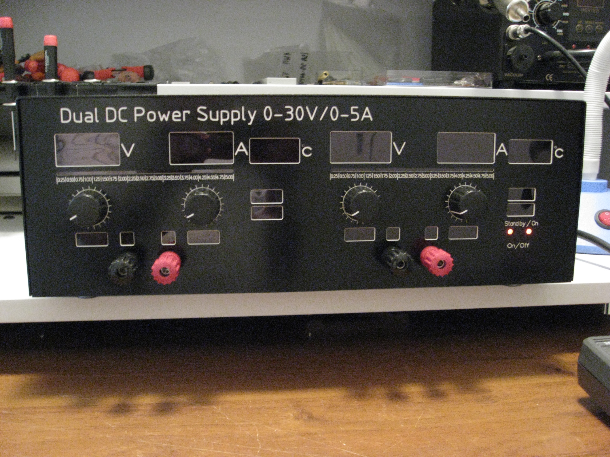 **broken link removed**
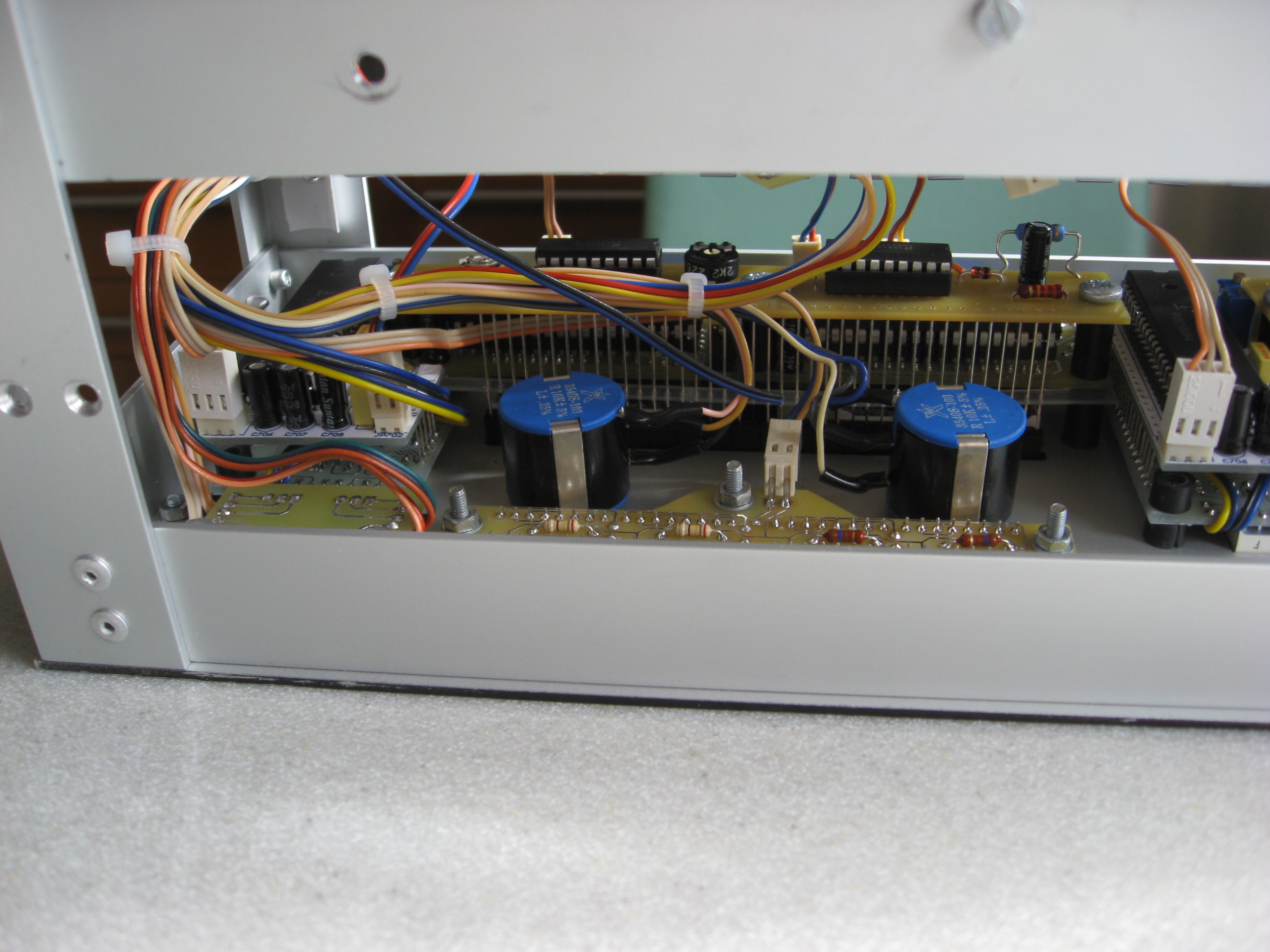


Link to original thread (some useful attachments) - Zasilacz 2 x 30VDC 5A