Continue to Site

Welcome to EDAboard.com

Welcome to our site! EDAboard.com is an international Electronics Discussion Forum focused on EDA software, circuits, schematics, books, theory, papers, asic, pld, 8051, DSP, Network, RF, Analog Design, PCB, Service Manuals... and a whole lot more! To participate you need to register. Registration is free. Click here to register now.

Power supply 0-40VDC, 0-2A

Status
Not open for further replies.

mrcube_ns

Advanced Member level 1
Joined
Apr 10, 2002
Messages
452
Helped
48
Reputation
96
Reaction score
34
Trophy points
1,308
Location
Europe
Visit site
Activity points
3,813
Hello friends,

I want to make power supply which is controlled by PIC mcu (with filtrated PWM outputs for current and voltage limit) and with LCD for show voltage and current measurements.
I tried to find some good schematics for this and didn't succeeded :-(.

I need IDEA how to do this. So, some internet links, or schematic with similar designs is enough for me.


Thank You in advance!


Mr.Cube
 

I want to make power supply which is controlled by PIC mcu (with filtrated PWM outputs for current and voltage limit) and with LCD for show voltage and current measurements.
I tried to find some good schematics for this and didn't succeeded .

I need IDEA how to do this. So, some internet links, or schematic with similar designs is enough for me.


Thank You in advance!


Mr.Cube
Hi Mr.Cube
That's so simple ! it is enough you create PWM signal with your MCU and then use a float driver e.g IR2117 . and then a filter and then a feedback to your ADC !
How much is your input voltage ? where it is coming from ? main power line ? or perhaps a transformer ?
Best Wishes
Goldsmith
 

That's so simple ! it is enough you create PWM signal with your MCU and then use a float driver e.g IR2117 . and then a filter and then a feedback to your ADC !
Yes, this is my general idea, to use PWM signals to control voltage and current limit, and with ADC to read voltage and current and show them on display. I try something which I think out last night and it works, but I want to see schematics of working power supplies just to see if someone make better solution...

How much is your input voltage ? where it is coming from ? main power line ? or perhaps a transformer ?
I order transformer 220VAC/36VAC 200VA, I made calculation that in worst case I have 42V input voltage to stabilizer:
- worst LO case is that input main voltage is 200VAC, in that case I'll get 32.7VAC on secondary, which means that I have 46.3V after diode bridge in peak, when I reduce this by 1.4V (two diodes in bridge), and reduce by ~2V for voltage drops on filter capacitors (when current is 2A) I get a about 42V.
- worst HI case is that input main voltage is 240VAC, in that case I'll get 39.3VAC on secondary, which means that I have 55.5V after diode bridge in peak, when I reduce this by 1.4V (two diodes in bridge), and reduce by ~2V for voltage drops on filter capacitors (when current is 2A) I get a about 52V.

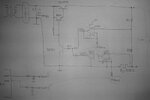
Here is schematic which I tried (with difference that Vref1 and Vref2 I made with trimmer 10kOhm, never used PWM on PIC before so this was faster for test):

2012-12-19 09.17.27.jpg

Mr.Cube
 
Last edited:

Status
Not open for further replies.

Similar threads

Part and Inventory Search

Welcome to EDABoard.com

Sponsor

Back
Top