Continue to Site

Welcome to EDAboard.com

Welcome to our site! EDAboard.com is an international Electronics Discussion Forum focused on EDA software, circuits, schematics, books, theory, papers, asic, pld, 8051, DSP, Network, RF, Analog Design, PCB, Service Manuals... and a whole lot more! To participate you need to register. Registration is free. Click here to register now.

Power MOSFET testing

Status
Not open for further replies.

netloginkk

Newbie level 5
Newbie level 5
Joined
May 7, 2010
Messages
10
Helped
0
Reputation
0
Reaction score
0
Trophy points
1,281
Location
Hyderabad / Vizag
Visit site
Activity points
1,360
Hi,

I am testing IRF4905.
(Datasheet: http://www.irf.com/product-info/datasheets/data/irf4905.pdf )

For measuring RDS(ON), at VGS=-10 and ID=-38A, i have used the following circuit
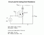
Drain_Resis.gif

The drain resistor is a rheostat.
After applying pulsed gate voltage, i am varying VDD (10V to 30V) and the rheostat to get ID=38A (ammeter reads average, so 0.76A in ammeter is 38A peak (2% duty)).

Now i measure the drop between drain and source (VDS) using a DMM. so RDS(ON) = VDS/ID

I want to know whether this procedure to measure RDS(ON) is correct. The datasheet indicates a note at ID=-38A (pulsed current, 2% duty), but i managed it by switching gate. Do i need to keep the gate at -10V (constant) and apply a pulsed voltage to drain.

Could anyone suggest a better circuit or method.
 
Last edited by a moderator:

This is an interesting question, and I would like to know the answer myself, so I asked a very experienced Power Applications engineer. The first response (this post) is the simplest and most direct approach. This is a DC approach. Later we can think about the pulsed approach.

This will all be in terms of an nmos because it is easier to think about the polarities that way. You can adapt this approach for the pmos.This approach is based on using the functions of a power supply. Suppose you want to test your power nmos at 10A. Assume a somewhat larger than expected RDS(on), say 2 Ohm. Then 10A into 2 Ohm is 20V. Set your power supply to 20V. Next, with the supply set to 20V, and the current limit set to zero, short out the supply. The output voltage will go to zero. Next, slowly increase the currrent limit until you reach 10A. This is not bad for the supply. It can work all day like this, it is in current limit mode, and is now working as current source for you.

If you want a more accurate reading of the current limit, you can place a current meter inbetween the + and - leads from the supply.

After making the current meter measurement, remove the current meter. The current source from the supply won't change as long as you don't touch the dial for current limit.

Connect a low impedance to the gate of your power nmos, say 50 Ohm. This to provide ESD protection to the gate. Connect VGS to the power nmos, but start with VGS=0. Now slowly increase VGS until you get to VGS=10V. The drain of the nmos is connected to the + output of your supply.

As VGS is turned ON, the power nmos comes to life and sucks the 10A limit from the supply. You can read the voltage on the supply or use a DMM to read the voltage on the drain. Obviously, this voltage divided by 10A is your RDS(ON).

The only problem with this approach is the availability of a high current power supply. But really, the power FET is in its triode region and the Ids -Vds curve is linear, so you can do the test at different (lower) currents. Maybe make 3 measurements (at I = 0.5, 1.0, and 1.5A) to verify linearity. Vds/Ids should be pretty much constant.

I'll wait for feedback to make sure my idea isn't crazy, and then I'll ask someone else about making the pulsed measurement. Sometimes this is the only way to go because of the high powers involved. There are some guys that I work with that make these measurements all the time, and I am happy for the opportunity to learn more about it. It would also be good to hear from anyone who characterizes power FETS.
 
Thank you for the reply.

But if you connect the power supply directly to drain, then Vds is equal to your supply voltage. So you will burn the FET.
 

As you increase VGS the FET will become a low impedance (this impedance is the RDS(ON) of the FET). The power supply has limited compliance. It cannot support any voltage with any current. As the current becomes large, the output of the supply will fall. This is what it means to become "current limited". The supply is no longer producing the voltage that you set because the current that we are drawing out of the supply has reached the current limit that we have set. For example, if we set the supply to be 20V, and we try to measure the voltage across a 0.1 ohm resistor the supply would have to drive 20/0.1 = 200A in order to support 20V. It can't do that; it doesn't have the ability to source 200 A. It will source as much as it can (the limit that you set), and the actual voltage that will show up is the current limit multiplied by whatever resistance we have across the supply. So the idea for the RDS(ON) measurement is the same. The output voltage will be the current limit that you set multiplied by the RDS(ON). You know the current limit that you set, so by measuring the voltage on the drain you can get RDS(ON).

To be even safer, check the data sheet for the FET and look for its absolute maximum VDS. Set the supply voltage lower than this. Then do the experiment with the supply by shorting it and setting the current limit.

I haven't done this myself, but I did talk to some guys in their 60s who have been doing this for many years. It seems clear to me that it will work.

I was talking a little later (after my first reply) with another one of these guys who makes these measurements. He always does pulse tests. The reason is that he doesn't want to heat the FET. The RDS(ON) will be temperature dependent, and you really want to get a value for it before heating occurs. He starts with the VGS at 10V and then applies a pulse to the supply (his supply already produces a known current source, so he doesn't have to do the current limiting procedure that I have described). He then captures the voltage on the drain with his scope. I don't know how long his pulse is, maybe 500 ms. Heating can occur quickly.

There is one other guy, who I believe has been making RDS(ON) measurements lately. If I can get his method, I'll let you know. Good luck, and I'd be interested to hear our your work goes.
 
... i measure the drop between drain and source (VDS) using a DMM. so RDS(ON) = VDS/ID
1. You'll be measuring the average value of VDD (98% of time) and VDS (2%). Make sure this is accurate enough. Better measure between the neg. terminal of VDD and the drain.
2. Make sure your DMM actually measures the average (mean) value.
 
Thanks for the reply... and sorry for taking long time (i was busy with other work).

I will try the continuous current test. But i am more interested in pulse test as most of the times i have to do pulse test.

David Levy;1193051 [B said:
He starts with the VGS at 10V and then applies a pulse to the supply[/B] (his supply already produces a known current source, so he doesn't have to do the current limiting procedure that I have described). He then captures the voltage on the drain with his scope.

Do you mean pulse of 10V is applied to gate or constant 10V at gate and pulsed voltage at drain. If pulsed voltage at drain is given how do you manage to pulse high current.

- - - Updated - - -

..... Better measure between the neg. terminal of VDD and the drain....

You mean to measure the 98% of VDD and then get the 2% VDS.
Yes i need to check my DMM... average. Thank you...
 

Mr.David Levy,
Tested RDS(ON) for continuous current upto 5A (max. continuous current is 52A and pulsed current is 260A), but the device is getting hot.

Thank you for the help, I just started to understand POWER MOSFET.

Just curious about pulse test.
 

The pulse test shouldn't be any different, except that you will need an accurate measurement with a fast settling time, so a DMM won't work. You'll likely need a current shunt for current measurement, and both the shunt voltage and Vds will need to be amplified a bit, so that offset errors on your oscilloscope don't dominate.
 

But i have a continuous power supply of 20A. How do i switch it on and off for getting low pulse widths. Do i need to use a MOSFET (apply pulse to gate and supply between drain and source) to get pulsed o/p and apply to drain of mosfet (DUT).
 

Status
Not open for further replies.

Similar threads

Part and Inventory Search

Welcome to EDABoard.com

Sponsor

Back
Top