Continue to Site

Welcome to EDAboard.com

Welcome to our site! EDAboard.com is an international Electronics Discussion Forum focused on EDA software, circuits, schematics, books, theory, papers, asic, pld, 8051, DSP, Network, RF, Analog Design, PCB, Service Manuals... and a whole lot more! To participate you need to register. Registration is free. Click here to register now.

Power Factor Correction

Status
Not open for further replies.

fethiyeli

Full Member level 4
Full Member level 4
Joined
Feb 9, 2013
Messages
207
Helped
10
Reputation
20
Reaction score
12
Trophy points
1,298
Visit site
Activity points
2,986
Power Factor Correction for SMPS

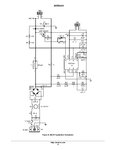
Hi Everyone, I have push-pull DC-DC converter that converts 30VDC into 311VDC, three level PWM inverter and battery charger. The question is that ı need to add PFC circuit for SMPS due to 1kVA output power and ı dont know how to add PFC circuit before SMPS. 30VDC is minimum of three 12V 7AH battery voltage. I have a circuit like below. Its output voltage is higher than input of SMPS. So, how can ı use PFC for my SMPS ? Is it possible to use this PFC for my SMPS ? I gues ı can use this PFC with SMPS having 1:1 transformer but another issue appears when ı want to increase 30VDC into 311VDC.
AND8322-D_Page_10.jpg
 
Last edited:

yes, during power cut, there is no need to add PFC circuit when we use the batteries. But ı cant use the batteries all time. If I have energy in AC line, ı have to use ac line. In fact, ı have controlled rectifier which converts 220VAC in to 50VDC. ı use this 50VDC for SMPS input and output of SMPS becomes approx 311VDC. I use this DC voltage for h-bridge DC bus of the inverter that has 220VAC pure sine wave output. During power cut, total voltage of three series of batteries falls up to 30VDC. So, input of the SMPS becomes now 30VDC but output stays as 311VDC like before. 50VDC and 30VDC are necessary for battery charger input. If, you have better idea, pls share it with me =) ı really need it =)
 

You probably need to start over with the 50V power supply (sorry!). The SCR-fed front-end is totally incompatible with power factor correction because the SCR duty cycle is so low. You basically need a conventional 240VAC input-50VDC output power supply: a PFC front end which will generate a 400V or so DC link, followed by a 1kW DC-DC converter that converts the 400V to 50V.
 

Why you need PFC for a battery powered converter?

ofc i dont need when energy is provided from battery, i need it when there is energy at AC line. Battery is only used when there is no energy at AC line.
 

Ok, i think you want to do so called on-line UPS, double conversion. In this case, there a comon DC rail of 311V that came from AC/DC converter and use this converter when AC is present; when AC fail, there are a boost converter that boost from 24-36 or any other battery bank voltages to same DC rail of 311V that feed an inverter which provide AC output voltage. PFC is used in AC/DC converter to improve PF. In your case there are too many linked convertes and efficiency is bad. If don't need online UPS, may use a relay to switch UPS output from direct AC line to inverter. Much more simple.
 
Ok, i think you want to do so called on-line UPS, double conversion. In this case, there a comon DC rail of 311V that came from AC/DC converter and use this converter when AC is present; when AC fail, there are a boost converter that boost from 24-36 or any other battery bank voltages to same DC rail of 311V that feed an inverter which provide AC output voltage. PFC is used in AC/DC converter to improve PF. In your case there are too many linked convertes and efficiency is bad. If don't need online UPS, may use a relay to switch UPS output from direct AC line to inverter. Much more simple.

Exactly. I have already had a SMPS that boost 30VDC (least battery voltage) to 311VDC. I have also controlled rectifier that rectifies 220VAC into 50VDC that is used for battery charging. DC bus before SMPS, varies between 30VDC and 50VDC. If i use PFC, i dont know where to put in this system. Best PFC topolgy is boost type but its output is about 385VDC. In order to get 220VAC from inverter that 385VDC must be decreased to 311VDC and it also must have very low ripple. After this PFC, i need to use buck converter to decrease voltage into 311VDC with low ripple.

When AC line on, 220VAC--->50VDC--->311VDC--->220VAC.
When AC line off, 30VDC--->311VDC--->220VAC.

Now if i want to add PFC, how can it be put in this system ?

But i ensure that i need to redesign a battery charger that can use this 385VDC or 220VAC directly.
 

PFC for controlled rectifiers are not simple. In this case I think, you need to calculate advantage of added PFC feature vs cost; simplest way seem to keep actual rectifier to be used as charger only and make a new uncontrolled rectifier (fixed 36V output) with included PFC (will be a bridge rectifier + boost/PFC converter + buck converter).
 

    V

    Points: 2
    Helpful Answer Positive Rating
PFC for controlled rectifiers are not simple. In this case I think, you need to calculate advantage of added PFC feature vs cost; simplest way seem to keep actual rectifier to be used as charger only and make a new uncontrolled rectifier (fixed 36V output) with included PFC (will be a bridge rectifier + boost/PFC converter + buck converter).

Ok thnx dude. I also think like that. If i encounter with a problem, i write here.
 

PFC for controlled rectifiers are not simple. In this case I think, you need to calculate advantage of added PFC feature vs cost; simplest way seem to keep actual rectifier to be used as charger only and make a new uncontrolled rectifier (fixed 36V output) with included PFC (will be a bridge rectifier + boost/PFC converter + buck converter).

PFC for controlled rectifiers are not simple???? How about impossible? You cannot have unity power factor (unless you want to play naming games with displacement power factor, true power factor, and distortion power factor) without in-phase continuous sinusoidal current for a sinusoidally applied voltage. The SCR current waveforms are non-sinusoidal.
 

As you know, PFC mean power factor correction and don't mean PF=unity (=1); PFC block try to have PF as close to unity. PF can be correct even in controlled rectifiers, it's very possible, but not easy; SCR is not only one device for controlled rectifiers and current shape is imposed by load and controller not by device type. See **broken link removed**
 
As you know, PFC mean power factor correction and don't mean PF=unity (=1); PFC block try to have PF as close to unity. PF can be correct even in controlled rectifiers, it's very possible, but not easy; SCR is not only one device for controlled rectifiers and current shape is imposed by load and controller not by device type. See **broken link removed**

I know Tom Lipo. A company I worked for was a member of Wisconsin Electric Machines and Power Electronics Consortium. I have built SCR power supplies for years including 12-pulse and 24-pulse machines. Yes, you don't have to try to achieve 1.0pf. And you can increase the power factor of an SCR-type machine from something like 0.5 to something like 0.7 with adequate line L. If you want to do harmonic re-injection then you can achieve typical line-quality numbers like 0.9 - 0.95 (which is what most customers want when they say they want a power factor corrected power supply). However reinjection is a complex task generally reserved for computationally intensive topologies and the circuit included by fethiyeli was a one-chip analog controller.

And you are right I didn't include other kinds of controlled rectifiers than a silicon controlled rectifier. Of course it seems unlikely that a person asking for help adding pfc to a "controlled rectifier" system would have the technological knowledge of exotic controlled rectifiers. This makes a much sense as saying we were really talking about building precision rectifier circuits when we used the term rectifier. Occam's Razor please.

- - - Updated - - -

By the way, if you read the Lipo paper, they reduced the input current distortion from 27% to 11%, but they also added a lagging power factor to extend the conduction time. So they were nowhere near 0.9pf.
 

Yes, for SCR is hard to improve PF and even worse for high power SCR. With IGBT may reach very good PF in controlled rectifiers. In most cases improve in PF will lead in distorsion reduction, very important point especially for goods covered by regulation standards requirments.
 
Status
Not open for further replies.

Similar threads

Part and Inventory Search

Welcome to EDABoard.com

Sponsor

Back
Top