Continue to Site

Welcome to EDAboard.com

Welcome to our site! EDAboard.com is an international Electronics Discussion Forum focused on EDA software, circuits, schematics, books, theory, papers, asic, pld, 8051, DSP, Network, RF, Analog Design, PCB, Service Manuals... and a whole lot more! To participate you need to register. Registration is free. Click here to register now.

Portable VLF Antenna Help

Status
Not open for further replies.

cmm5559

Newbie level 3
Newbie level 3
Joined
Feb 5, 2013
Messages
4
Helped
0
Reputation
0
Reaction score
0
Trophy points
1,281
Visit site
Activity points
1,332
My boss is asking me to construct a VLF unit to detect ground fractures. I understand the principles and have a general construction scheme laid out but I know absolutely nothing about RF antennas. I'm trying to mimic an discontinued unit that we currently posses. It's instruction manual is a very high level description of what it has inside. It contains "two 15 cm long ferrite-rod antennas, each wound with thousands of turns of wire."

We are looking to receive the 24 kHz frequency from Maine. Our existing unit was constructed in the 60's so I am trying to to learn three things:

1.) What kind of ferrite rod and wire do I use?

2.) How many wraps of wire do I need to get down to 15 to 30 kHz range?

3.) I would like to improve on the unit from the 60's, can I use smaller rods/better wiring to cut down on size and weight?

This is nowhere near my area of expertise so any help would be greatly appreciated.

Thanks in advance.
 

24KHz isn't a particularly low frequency so the inductance of the antennas shouldn't need 'thousands' of turns of wire.

I have to confess this isn't my field of expertise either but it sounds like you have a simple VLF receiver, I'm not sure why two ferrite rods are needed though unless they are mounted at 90 degrees to each other to avoid signal nulling. Is it possible for you to post a picture of the unit to give us a better idea of what you are trying to emulate?

The basic operation of a VLF receiver is to use tuned circuits at the desired frequency, then an amplifier to increase the signal level, followed by some sort of measurement system. This could be a meter (analog or digital) or an acoustic output. Given that the original is around 50 years old, it should be possible to make a more efficient version now but some physical factors may restrict it's minimum size.

The number of turns on the rods is impossible to predict without knowing the type of Ferrite and the value of any parallel capacitances. The resonant frequency is "2 * pi * SQRT( L * C)" where C is probably a fixed capacitor connected across the coil, the frequency is the one you want to monitor, in your case 24KHz and L is the inductance of the coil. The value of L depends on the number of turns and by how much the Ferrite is increasing it. There are many different grades of Ferrite, each having different properties. With so many variables it's impossible to say how many turns should be on the coil. In general though, you can compensate for shorter Ferrite rods by increasing the number of turns or increasing the capacitance across it. The thickness of wire also influences the inductance but not anywhere near as much as the number of turns so with shorter rods if you use thinner wire you should be able to squeeze the extra turns on it. Alternatively, if there is space, you can wrap more than one layer of wire, making it fatter rather than longer.

Brian.
 

All I can add to what Brian already wrote is that by changing the length to diameter ratio of the ferrite rod you can modify the radiation pattern of the antenna i.e. longer and thinner rods will make a "less directional" antenna.
 

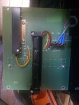
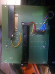
I opened up the original last week to get a feel for how their antenna was designed.
2002-12-08 12.00.jpg

It has two ferrite rods, one vertical and one horizontal. They are shorter than 15 cm, they are just over 4 inches. They way it works is one receives the direct signal from the transmitter and the other receives a distorted signal and the two are compared to give us the ability to see the underground fractures.

Currently one must be aligned correctly to receive the best signal and we are planning on a third axis antenna to help remove that step.
 

Attachments

  • 2002-12-08 12.00.00-11.jpg
    2002-12-08 12.00.00-11.jpg
    2.3 MB · Views: 103

there are a lot of ferrite rod vlf antenna hits on google, such as this one:

users.tpg.com.au/users/ldbutler/Ferrite_Loop_Ant.pdf

indeed, thousands of turns do not seem to be out of the question. look at your circuit to see if there is a "tuning capacitor" in parallel with the turns.
 

Interesting article - including the bizarre spelling mistake!

From the photographs, it appears one rod is screened and has four wires, the other is open and has three wires. Presumably this is something to do with impedance matching. I'm suprised they are in the same orientation, I was expecting an X-Y arrangement. I have no idea of the mechanism that allows fractures to be detected, I'll do some research. What kind of fractures are you detecting? Is it geological or in pipework?

Given it's manufacture date, it almost certainly doesn't use anything other than discrete analog circuits and probably doesn't use FET devices. I can't remember exactly when FETs became readily available but I'm guessing it wasn't until the early 70s. (I must be getting old !)

Brian.
 

Interesting article - including the bizarre spelling mistake!

From the photographs, it appears one rod is screened and has four wires, the other is open and has three wires. Presumably this is something to do with impedance matching. I'm suprised they are in the same orientation, I was expecting an X-Y arrangement.

it seems to me that the second rod is on the other side of the PCB and is indeed perpendicular to the one visible. I think the element with 4 wires is/are tuning capacitor/s for both, a tuning screw is also visible. I cannot see any impedance matching.
Piotr
 

it seems to me that the second rod is on the other side of the PCB and is indeed perpendicular to the one visible. I think the element with 4 wires is/are tuning capacitor/s for both, a tuning screw is also visible. I cannot see any impedance matching.
Piotr

I'm sorry about that I forgot to describe what was on the board. From what you can see there is one vertical antenna and the horizontal antenna is on the reverse side of the pcb. The unit in the upper left is not a capacitor, I'll have to follow the wires and see if there is one elsewhere on the unit, it is actually an inclinometer. To properly detect the geoplogical fractures underground. They are usually water bearing and that makes them easier to detect.
 

I'm sorry about that I forgot to describe what was on the board. From what you can see there is one vertical antenna and the horizontal antenna is on the reverse side of the pcb. The unit in the upper left is not a capacitor, I'll have to follow the wires and see if there is one elsewhere on the unit, it is actually an inclinometer. To properly detect the geoplogical fractures underground. They are usually water bearing and that makes them easier to detect.
if it is a capacitive liquid inclinometer then it could still be a part of tuning circuit...
 

Thanks for the explanation.

I'm, still mystified as to how it actually works. I understand the principles of ground penetrating radar but that is usually done by utilizing the ground attenuatiion and propagation delays and hence needs a reference pulse transmitter but from your description this uses a fixed and I would guess distant constant transmission. GPR normally uses much higher frequencies anyway. I'm puzzled as to what property of the signal is changed by a fracture that could be picked up in the low EM spectrum. From experiments I did 40+ years ago with surface to underground signalling, I remember the signal attenuation from 'normal' moderately moist ground, rises sharply above around 2 - 5 Hz so I doubt it's using any method of conduction. I wonder if this is an early magnetometer?

Brian.
 

To get the maximum Q out of the coil it must be wound with Litz wire. I would start by buying some ferrite rod aerials for transistor sets with a LONG WAVE winding. This is as near as you will find ready built. If you cannot achieve a decent L/C ratio, slip more of the long wave windings onto the one piece of ferrite and connect them in series (watch out for the phasing!). One whizz for giving a ferrite rod aerial more directivity, is to put it in a large diameter metal(copper or ali ) tube (say 50mm) which is slit right down its length, so as not to make a short circuit turn.
Frank
 

Status
Not open for further replies.

Similar threads

Part and Inventory Search

Welcome to EDABoard.com

Sponsor

Back
Top