Myself1247
Newbie level 4
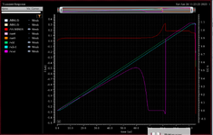
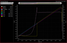
Hello everyone, I am trying to design a por with supply voltage- 1.08V to 3.6V, supply current- 1u to 2u and trigger voltage- 0.6V to 0.9V. I am using LBC9 in cadence. I have tried many architectures and currently i have designed a por with NAT mos as current reference. I have done the simulation for strong 125°C and weak -40°C. for strong the trigger is at 480mV and for weak at 888mV. please suggest me how to shift the trigger voltage to atleast 600mV.
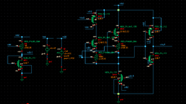
circuit description:
initially the NAT current is more than the current due to MN4 hence the net1 is pulled up and output is 0V, since the supply voltage is ramping the current through NM4 will increase and at some point would overpower the NAT current and thats how we get a trigger voltage. The PMOS MP0 is used to add hyteresis to the circuit.
Any suggestion is welcomed.
thanks