Continue to Site

Welcome to EDAboard.com

Welcome to our site! EDAboard.com is an international Electronics Discussion Forum focused on EDA software, circuits, schematics, books, theory, papers, asic, pld, 8051, DSP, Network, RF, Analog Design, PCB, Service Manuals... and a whole lot more! To participate you need to register. Registration is free. Click here to register now.

PNP transistor not switching properly

Status
Not open for further replies.

engineer.amir@hotmail.com

Newbie level 4
Newbie level 4
Joined
Aug 27, 2010
Messages
7
Helped
2
Reputation
4
Reaction score
2
Trophy points
1,283
Activity points
1,343
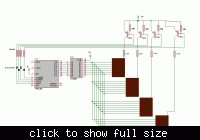
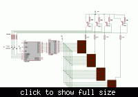
Below is the circuit diagram in which I am having the PNP switching problem. PNP keeps ON the seven segments and doesn't perform switching. I have changed the Emitter to Base resistance and controller to base resistance either but still not effective. Where is the problem ....???? I have also used the ULN2803 between MCU and Transistor to ensure the proper sink and source but that was also useless..... any comments that may help me out ????

View attachment seven seg PNP.bmp
 

The circuit doesn't work because a PNP transistor supplied from 12V can't be controlled by 5V logic without a level converter. A source driver like ULN2981 could be used to perform both, level conversion and switching. Also 2803 could basically act as level converter in a suitable dimensioned circuit.

You are apparently intending a per-digit current limiting with R5 - R8. Of course, 100k is an absurd dimensioning for it, please consider ohms law and the specified display opreation current. But you should provide per segment current limiting, to achieve a constant segment current.
 

Hi,

I think 2.2k resistors for R5-R8 will be fine (limiting curent to 5mA witch is suffisent for most 7 seg led displays), but, put them on the collector side (between collector and 7seg).

To drive your PNP FvM is right when the mcu output is high (+5V) it's still low for the TIP42 witch have his emitter at +12V.
What you have to do is just add diodes (1N4148 will be fine) between the mcu outputs and 10K resistors (K on mcu, A on 10K resistor), and re-use your 100k resistor between bases and emitters of TIP42s.

I think all these together will do the job.
 

Look sharp, the suggestion solves none of the addressed problems. The diodes are simply useless.

Traditionally, a 7407 open collector driver has been used as a level converter to drive out to 12V level. NPN transistors in common base circuit would be suited as well.

Please review also my comment about digit versus segment current limiting.
 
Last edited:

OH! Shame on me, I've made a big mistake, thanks FvM for correcting me.

In this case replace 1n4148 diodes by 7.5volts zener diode opposite way (Anode on mcu, cathode on 10k resitors).


Zener diodes can possibly work. Please consider that the driver threshold is at about 7 uA, set by the 100 k resistors. The zener voltage will be considerably lower than 7.5V at this current, so most likely, the transistors still won't turn off. The 100 k should be reduced to e.g. 3.3K to achieve a clear switching. You can even omit the zener diodes and adjsut the voltage divider respectively. But the operation would rely on correct supply voltage level then.

As said, you should have individual 2.2k resistors in the ULN outputs for constant segment currents instead of one common resistor per digit.
 

I agree with you FvM.
 

Status
Not open for further replies.

Part and Inventory Search

Welcome to EDABoard.com

Sponsor

Back
Top