mailus
Full Member level 4
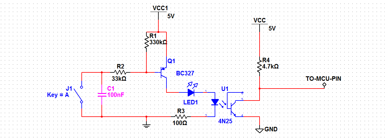
I want to drive a Opto-coupler through a Transistor.
when my input is zero(below 2.5V) the transistor should turn on to drive opto-coupler.
if my input is greater than 2.5V means the transistor turn off.
how to calculate the biasing resistor and which bias is preferred?.
this circuit is used with microcontroller operated with 5V power supply
when my input is zero(below 2.5V) the transistor should turn on to drive opto-coupler.
if my input is greater than 2.5V means the transistor turn off.
how to calculate the biasing resistor and which bias is preferred?.
this circuit is used with microcontroller operated with 5V power supply
")