Continue to Site

Welcome to EDAboard.com

Welcome to our site! EDAboard.com is an international Electronics Discussion Forum focused on EDA software, circuits, schematics, books, theory, papers, asic, pld, 8051, DSP, Network, RF, Analog Design, PCB, Service Manuals... and a whole lot more! To participate you need to register. Registration is free. Click here to register now.

PNP and NPN alternate switching

Status
Not open for further replies.

piyushpandey

Member level 4
Joined
Mar 26, 2012
Messages
70
Helped
0
Reputation
0
Reaction score
0
Trophy points
1,286
Activity points
2,051
Hello guys


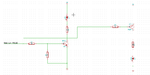
I have made following circuit simple one in which I want to make one transistor on when I provide the high pulse( NPN ) and make another transistor on when I provide low pulse ( PNP ).


The schematic is here:

adc.png


what I have seen that when I am testing the PNP and NPN individually than I am getting the switching correctly form both transistors.

But when I have made connections as per in the schematic and have made the base of both NPN and PNP common so that when I put the high pulse the
NPN gets on and when I put the low pulse the PNP gets on .

But what I am getting the result on the breadboard is that when I made the base of two NPN and PNP common to receive the input, both the leds start glowing without any pulse on the high_low_pulse terminal , actually that terminal is nothing but a wire on my breadboard which I use to connect to VCC for the high pulse and to GND for the low pulse.


why I am getting this unusual behaviour .


Also I have checked the voltage levels at the pnp and npn which are as follows:

PNP :

Emitter == 5.08 V

Base == 4.41 V

Collector == less than 1 V


NPN :

Emitter == 0 V

Base == 0 V

Collector == 3.52 V


according to this the emitter-base junction of the PNP transistor is forward bias and the colector-base junction is reverse biased .

whereas in case of NPN the base-collector are reverse biased .


I want to know do I am getting correct voltage values on the transistor terminals.


Thanks
 

Attachments

  • adc.png
    adc.png
    16.8 KB · Views: 89

it seems that the PNP dose not work in switch mode,it is better to add the PNP Collector resistor to 4.7k and make the Ic/Ib<20
 

it seems that the PNP dose not work in switch mode,it is better to add the PNP Collector resistor to 4.7k and make the Ic/Ib<20

Thanks zheng

for your reply but unfortunately it is not working by replacing the 100 ohm collector resistor with the 4.7 k ohm and can you tell me how to make the base current of PNP transistor less than 20.


Thanks
 

please find the details
and I think it is better to change the resistor to 510ohm,and 100ohm should be also ok,
and if there are some welding errors?
pnp_npn_schematic.png
npn_pnp_result.png
 

there is a differnce between a connection to 0V, a connection to Vdd, and no connection at all. In the first two cases, the input will force one transistor on, and one off. In the last case, current can flow from Vdd to the PNP's base, through the resistors, through the NPN's base, to ground.
 

there is a differnce between a connection to 0V, a connection to Vdd, and no connection at all. In the first two cases, the input will force one transistor on, and one off. In the last case, current can flow from Vdd to the PNP's base, through the resistors, through the NPN's base, to ground.

yes permute you are vvery well true and this is what exactly happening .

when the wire through which I am not providing the high and low by connecting to the Vdd and GND respectively, I am getting bot the transistors in on condition due to which both the LEDs are glowing.

and when I provide either Vdd and GND voltage than only one transistor is on.


Actually the concept which I want to implement is that I want to control the two LEDs with the single micrcontroller pin i.e. when the terminal is high the NPN will be on and when it is low the PNP will be on but since the base of both of them is common and there is approximately greater than 4 V on the base of the PNP and less than 1 V on the base of the NPN the current flows from PNP to NPN and therefore the two transistors gets on , which I don't want because I want to use this high impedance state also to light another set of leds keeping this set off.

can you suggest any solution to this problem.


Thanks
 

Use the collector of the first NPN to drive another NPN rather than using a PNP.

Keith
 

There is a way to use a single transistor to alternate between 2 led's.

Click the link below to open an animated simulation that plays on your computer.

It opens a website called falstad.com. Click 'Allow' when asked to permit the connection.

https://tinyurl.com/6w6esgr

The layout at the left has a diode inline with one led to reduce a dim glow when idle.

The layout at right is an alternate method included just for variety's sake.

You can alter values at will, by pressing ctrl (or alt) key, and clicking a component, to bring up an edit window.

However now I see you want to turn off both led's by making your microcontroller output show high impedance. This means the above method will not do what you want.
 
Last edited:

yeah its a good link bradth the rad I appreciate it and I ma amazed that why I didn't think of it but yeah I want to use the high impedance condition too therefore it is not that much worth it.


any way thanks for providing this beautiful animated link.
 

After doing some more thinking and experimentation...

The link below shows a working schematic of what you want to do. Both led's are off when the controlling signal goes to high impedance.

The tactic is to put all loads in the emitter legs, and install diodes, so the sum total adds up to a greater volt threshold than 5V which is your supply V.

https://tinyurl.com/7ufjjbs

When you click the switch so it is open, that is like your microcontroller going to high impedance.
41 uA flows through the led's. A miniscule amount.

The 68 ohm resistors permit 20 mA to go through your led's, around the safe limit. Adjust as desired.
 

Status
Not open for further replies.

Similar threads

Part and Inventory Search

Welcome to EDABoard.com

Sponsor

Back
Top