Continue to Site

Welcome to EDAboard.com

Welcome to our site! EDAboard.com is an international Electronics Discussion Forum focused on EDA software, circuits, schematics, books, theory, papers, asic, pld, 8051, DSP, Network, RF, Analog Design, PCB, Service Manuals... and a whole lot more! To participate you need to register. Registration is free. Click here to register now.

PLZ Help me with VCO TEST, THX!

Status
Not open for further replies.

djallon

Newbie level 4
Newbie level 4
Joined
Mar 18, 2012
Messages
7
Helped
0
Reputation
0
Reaction score
0
Trophy points
1,281
Visit site
Activity points
1,329
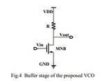
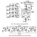
Hello, every guys. I test my VCO chip several days ago. The chip was fabricated in TSMC 0.18-um CMOS process through MPW. the test results show that the output frequency of vco is 4.4-6.9GHz, phase noise is between -70dBc and -85dBc. However, the output frequency is 4.3-6.6GHz and phase noise is -107~-117dBC in post-simulation, Then, there is my questions, What's going on with the VCO? Why is the test result of phase noise performance so bad? Do my test method or design have some problems? Which is the main problems? Please help me~Thank you so much! VCO电路图.jpg缓冲.jpg
 

Parasitic components/process variations/interconnections etc. impact much the oscillation frequency and that's why I find this difference of oscillation frequency as normal.But in term of Phase Noise, it's hard to say the same thing because the difference is huge.In order to say something, we should know measurement setup and Phase Noise nature ( which off-set frequency is used).
But the frequency shift seems to be normal.
You have also to make Monte Carlo simulation over 100 or 200 PSS run with temperature effect.In additional to this, Pareto simulation with stat. block will give you the sensitivity of the VCO based on components used.So, you can see which component is more impacting on VCO frequency.
 
Thanks very much! This is a supplementary. The offset frequency is 1MHz. The output frequency of test is Okay, but the phase noise is so terrible that I am upset about it. There, the chip is on-wafer measurement. I only make a filter capacitor of 400uF at point Vtune and don't make a filter at supply line. Do I need make a filter at every DC pad?
By the way, I am a new guy to VCO design. Could you introduce some articles about Monte Carlo and Pareto simulation of VCO? :p
 

Status
Not open for further replies.

Part and Inventory Search

Welcome to EDABoard.com

Sponsor

Back
Top