Continue to Site

Welcome to EDAboard.com

Welcome to our site! EDAboard.com is an international Electronics Discussion Forum focused on EDA software, circuits, schematics, books, theory, papers, asic, pld, 8051, DSP, Network, RF, Analog Design, PCB, Service Manuals... and a whole lot more! To participate you need to register. Registration is free. Click here to register now.

PLZ ASKING FOR HELP 4 UART PROBLEM 16F877a

Status
Not open for further replies.

shaker1

Junior Member level 1
Joined
Dec 21, 2010
Messages
15
Helped
0
Reputation
0
Reaction score
0
Trophy points
1,281
Activity points
1,409
Hello everybody iam a new member asking for ur help in doing my senior project.

i have a question for the pic's experts i hope they can answer me.

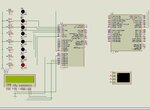
it is possible to control pic outputs pins by uart data? for example if i send a data 8bit through uart device to the pic rx it will stored in RCREG it possible to read these data and execute a command to send output to operate a relay connected to any outputs pin in the microcontroller.

my idea is to control pic outputs pins via tcp/ip through tcp/ip to uart interface card which is converts the tcp/ip to uart serial data and then send it ti pic rx.

Waiting for ur replays i will appreciates ur help.
 

Do you mean if i send 1 from UART, P0.0 device should be ON.
If i send 2 it should be off
for 3 & 4 means p0.2 should operate
for 4&5 other pin should operate
 
Hi,

Yes its quite easy to do that with a Pic, first you need to say what programming language you will be using, then look for one of the many online tutorials covering turning on a led ( or relay) and RS232 serial transmission.
 

dear ckshivaram

yes that exacly whats iam trying to do, each serial data value will control separte output pin
in summary
tcp/ip command will convert to serial

''0000 0001'' switch on RB1 "Relay 1"
''0000 0010'' switch swich off RB1 "Relay 1"
and so on for the other realys

can you help me in understanding some issues.

---------- Post added at 13:23 ---------- Previous post was at 13:16 ----------

dear wp100

i started writing my prgram in assembly bu i stacked in reading the 8bit data from the RCREG regersty how can i write instraction to do the following:

read the 8bit data in RCREG and if it equal to "1" switch on RB1 to high. ??


and i dont need to use RS232 circuit because iam using embedded serial uart card it will send and receive 3.3V ttl serial (that mean it can communicate directly with my pic but in between i will use a logic converter 3.3V to 5 V and opposite).

waiting ur replay

Hi,

Well I do not know if you can change your incoming data layout, it would be much easier if you did it like this.

''0000 0001'' switch on RB0 "Relay 1"
''0000 0000'' switch swich off RB0 "Relay 1"
''0000 0010'' switch on RB1 "Relay 2"
''0000 0000'' switch swich off RB1 "Relay 2"

This way you could simply read RCREG and copy it to PortB .

movf RCREG,W
movwf PORTB

If you want to use your original format then you will have to read RCREG and then Compare each bit to determine which Port to turn on or off,

Both the above assume you have configured PortB to be outputs

clrf PORTB
banksel TRISB
clrf TRISB
banksel 0
 
One simple thing is to write a switch case for every possible options

switch(n)
{
case '1': switch On RA0
break;
case '2': Switch Off RA0
break;
........................
}

Receive the character from UART and store it in a variable.( declare the variable as char). compare the received character with stored character in switch case... something as i have shown above.
i did not follow any syntax, so request others not to point compilation error in that
 
thank you i will go through ur site

---------- Post added at 22:48 ---------- Previous post was at 22:42 ----------

dear wp100

thank you for ur valuble advice, u are absoletly right ur way is more easier and i will flow it but i will face one problem what will happen if i want i want to keep RB0 on and switch off RB1 since iam using this command "0000 0000" all PORTB will switch off.

and when i need to clear these registes
clrf PORTB
banksel TRISB
clrf TRISB
banksel 0

before or after reading the RCREG and do i need to use any interpt in my case.

waiting ur replay.

---------- Post added at 22:50 ---------- Previous post was at 22:48 ----------

dear ckshivaram

is this a assembly instruction could u plz explain to me more.

switch(n)
{
case '1': switch On RA0
break;
case '2': Switch Off RA0
break;
........................
}

thank u 4 ur help

---------- Post added at 22:55 ---------- Previous post was at 22:50 ----------

can you plz check my program if it correct:

;=========================MAIN INITIALIZATION=========================================

#include <p16f877a.inc>


#DEFINE BANK0 BCF STATUS,5
#DEFINE BANK1 BSF STATUS,5

BANK1 ;Move to Bank1
movlw b'00000000'
movwf TRISB ;Set port B, I/O
BANK0 ;Return to Bank0


;=========================SERIAL/UART INITIALIZATION=========================================

clrf PORTA ;Make sure all ports cleared
clrf PORTB
clrf PORTC
clrf PORTD

BANK1 ;Move to Bank1
movlw d'25' ;Setup of baud rate = 9600pbs @4MHz
movwf SPBRG
movlw B'01100100'
movwf TXSTA ;SETUP FOR TXSTA REGISTER,ENABLE 9-BIT TRANSMISSION
BANK0 ;Return to Bank0
movlw b'11010000'
movwf RCSTA ;SETUP FOR RCSTA REGISTER,ENABLE 9-BIT CONTINUOUS RECEIVING

start
movf RCREG,W
movwf PORTB

end

=====================
plz correct me if i am doing any mistake
 

Hi,

Well think of each of the 8 bits as a bank of physical on / off switches.
When you change the switches that info is passed to and reflected on PortB

so -
sending 00000101 will turn on relays 1 and 3
sending 00000001 will turn off relay 3 but leave relay1 on
sending 00000110 will turn relay 2 and 3 on, relay 0 off.
This is all achieved by simply copying RCREG to PORTB


You also can send over the commands as you originally intended -

send 00000001 to turn on relay 1

send 00000010 to also turn on relay3

When you send over the second byte then you have to merge the new single setting onto PortB with needs a little bit of extra programming - will let you think about that :wink:


As for your program code - well you are getting there, but a few pointers.
You have Cleared the Ports but you needs to set their Direction ie Inputs or Outputs with the respective TRIS instruction.
Also see the Datasheet PORTA section for the code example of how to ensure you set the Ports to Digital rather than the default Analogue

Your Baud rate set up, a bit unusual in 9 bits ? - 8 data bits + 1 stop bit is more often used, or have you added both together ?

After that you have just said read the RCREG file, but you have not told it to receive any data !

Have a look at this tutotial for general info and at download example 7.7 which is for the 876/877 hardware Usart you are using.
PIC Tutorial* Seven - RS232
 
dear wp100,

my system is 8N1 8bit and one stop bit

as you said

so -
sending 00000101 will turn on relays 1 and 3
sending 00000001 will turn off relay 3 but leave relay1 on
sending 00000110 will turn relay 2 and 3 on, relay 0 off.
This is all achieved by simply copying RCREG to PORTB

this is very clear thank you i will follow this since it is simple way to achieve th outpots.

You have Cleared the Ports but you needs to set their Direction ie Inputs or Outputs with the respective TRIS instruction"

BANK1 ;Move to Bank1
movlw b'00000000'
movwf TRISB ;Set port B, I/O
BANK0 ;Return to Bank0

here i set the direction of poart B all as outputs, it is not correct

Also see the Datasheet PORTA section for the code example of how to ensure you set the Ports to Digital rather than the default Analogue
yes i will go through the setup and i will do it


Your Baud rate set up, a bit unusual in 9 bits ? - 8 data bits + 1 stop bit is more often used, or have you added both together ?

my baud rate is 9600 @4Mhz my communication is 9bit 8N1 one stop , it some thing wrong in my setup for uart intilization.

After that you have just said read the RCREG file, but you have not told it to receive any data !
here i have lack of knowlege since this is my first time working on uart i dont know how to write instrucation to recive the data and then write it on w then on port B if you have more examples i will appriate your help.

any way iwill go back again throgh ur replay and datasheet.
 

Hi,

Its always good practice to set the direction of all the ports on the chip.

Just wanted to check you were trying to send just 8 bits of data.

You need to work though this tutorial - download example 7.7 is for the 876/7 chip to apprieciate how the whole sequence works and how all the setting work together. Have used it myself so know its good.

PIC Tutorial* Seven - RS232
 

dear wp100,

according to the tutorial i modified the program can you plz check my program again and i have some question if u can answer me>

;Serial routines - write received bytes on PORTB


LIST p=16F877a ;tell assembler what chip we are using
include "P16F877a.inc" ;include the defaults for the chip
ERRORLEVEL 0, -302 ;suppress bank selection messages
__config 0x393A ;sets the configuration settings (oscillator type etc.)


cblock 0x20 ;start of general purpose registers
count ;used in looping routines


endc


org 0x0000

BANKSEL ADCON1
movlw 0x06
movwf ADCON1
BANKSEL PORTB ;turn analogue inputs off

Initialise
clrf PORTB
call SER_INIT ;initialise serial port
Loop call Rcv_RS232
goto Loop


;USART Serial routines

SER_INIT
BSF STATUS, RP0 ;select bank 1
MOVLW d'25' ;9600 baud @ 4 Mhz
MOVWF SPBRG
MOVLW b'00100100' ;brgh = 1
MOVWF TXSTA ;enable Async Transmission, set brgh
BCF STATUS, RP0 ;select bank 0
MOVLW b'10010000'
MOVWF RCSTA ;enable Async Reception
RETURN


Rcv_RS232 BTFSS PIR1, RCIF ; check for received data and shift to portB
GOTO Rcv_RS232
MOVF RCREG, W
MOVWF PORTB
RETURN


;End of serial routines

end

1)what the purpose of thesesteps
ERRORLEVEL 0, -302 ;suppress bank selection messages
__config 0x393A ;sets the configuration settings (oscillator type etc.)
since iam using external osillator

=======
is my understanding correct, i decide to follow ur advice iam going to use the following commands only.

1) "0000 0001" R1 only ON
2) "0000 0010" R2 only ON
4) "0000 0100' R3 only ON

6) "0000 0110" R1 OFF R2 ON R3 ON
5) "0000 0101" R1 ON R2 OFF R3 ON
3) "0000 0011" R1 ON R2 ON R3 OFF

8 ) "0000 1000" R1 OFF R2 OFF R3 OFF

so in this way i can control the three relays by writing RCREG 8bits into PORTB.
 

Hi,

Your code looks ok, I have just changed a couple of little things.

Code:
	org 0x0000
	
	BANKSEL ADCON1
	movlw 0x06			;turn analogue inputs off
	movwf ADCON1
	BANKSEL PORTB 
	
Initialise
	clrf PORTB
	BANKSEL	TRISB		; SET  TRISB TO DIGITAL OUTPUTS
	CLRF  TRISB
	BANKSEL 0

I have not checked all your buad rate settings in details, you can check those by sending your data across.
Start by sending just 00000000 and then a few seconds later send 11111111 across and see what happens.
Perhaps using a 470 ohm resistor and Led on each port while you are testing.


The Config is a complicated thing - the settings you have will work ok with a 4 meg xtal.
Again do not worry about that Bank error level mesages.

When you send your 8 bits of data it gets transfered to port B so you can control up to 8 relays on that port if you like, in any order or combination you like !

However you should give some thought to the practical application of relays.
Your program could switch the relays on and off every few milli seconds which will soon burn the relays and driver circuits out, so you need to include some protection by adding a delaying routine somewhere so you cannot do that so quickly.
Also it would be unwise to power all 4 or 8 relays on together as you would get a heavy power surge unless you designed a circuit to cope with the current draw of so many relays.

What are you going to use between the pic and the relay ? - the pic cannot drive a relay directly - look at the ULN2803A chip .
 
dear wp100,

thank you very much for a usful support and your technical advices, iwill try the burn the program into the pic and observe the results by scope.
 

Anybody plz can check this program for me, i tried to simulate in isis proteus 6 TX pin is continuos on uart not work properly :(


LIST p=16F877a ;tell assembler what chip we are using
include "P16F877a.inc" ;include the defaults for the chip

__config _CP_OFF & _XT_OSC & _WDT_OFF & _PWRTE_ON & _LVP_OFF & _BODEN_ON

CBLOCK 0x20 ;Declare variable address
dataL
ENDC


;
; -----------
; INITIALIZE
; -----------
;

org 0x0000
goto Start ; Jump to Start
org 0x0004


Start movlw 0x00
movwf PORTA ; Initialize port A
movlw 0x00
movwf PORTB ; Initialize port B
movlw 0x40
movwf PORTC ; Initialize port C
movlw 0x00
movwf PORTD ; Initialize port D

bsf STATUS,RP0 ; Bank 1
movlw b'00000000'
movwf TRISA ; All pins port A output (lcd display data)
movlw b'00000000'
movwf TRISB ; All pins port B output (Controlled Relays)
movlw b'10000000'
movwf TRISC ; All pins port C output except RC7/RX and RC0 for local check
movlw b'10000001'
movwf TRISD ; All pins port D output except RD (lcd display control and keypad inputs)
;
; -------------------------
; FUNCTION OF PORT A PINS
; -------------------------
;
movlw 0x06 ; All pins digital I/O
movwf ADCON1

;
; --------------------------------------------
; SET BAUD RATE TO COMMUNICATE WITH UART CARD
; --------------------------------------------
; Boot Baud Rate = 9600, 8 bit data ,No Parity, 1 Stop Bit
;

movlw D'25' ; 9600 baud rate
movwf SPBRG
movlw b'01100100' ; brgh = 1
movwf TXSTA ; enable Async Transmission, set brgh
bcf STATUS,RP0 ; Bank 0
movlw b'11010000' ; enable Async Reception
movwf RCSTA

;
; ------------------------------------
; PROVIDE A SETTLING TIME FOR START UP
; ------------------------------------
;

clrf dataL
settle decfsz dataL,F
goto settle
;
movf RCREG,W
movf RCREG,W
movf RCREG,W ; flush receive buffer

;
; ----------
; MAIN PROGRAM
; ----------
;

Main
call Check_status ;check if local control panel on or off

Control_Remote
call Receive_data ; wait for data
movwf PORTB ; Relays active
movwf TXREG ; echo data back to sender
call Send_data ; wait until finished sending
goto Main


;
; ----------------------------
; RECEIVE DATA FROM UART CARD
; ----------------------------
;

Receive_data btfss PIR1,RCIF ; check for received data
goto Receive_data
movf RCREG,W
return


;
; ------------------------------------
; WAIT UNTIL PIC IS FINISHED SENDING
; ------------------------------------
;

Send_data bsf STATUS,RP0 ; Bank 1
WaitHere btfss TXSTA,TRMT ; transmission is complete if high
goto WaitHere
bcf STATUS,RP0 ; Bank 0
return

;
; ---------------------------------------
; LOCAL USER CONTRL THROUGH LCD & KEYPAD
; ---------------------------------------
;

Check_status btfss PORTC,0
goto Control_Remote
goto Control_local

Control_local

bsf PORTC,1
goto Main


END
;
; ------------------------------------
; END OF THE CODE
; ------------------------------------
;
 

Hi,

As metioned before the VT sends data in Ascii format, so why not program up a second processor ( v7.6) to send the data to your 877a in simple binary so you can properly test your system.
You could also connect your Local / Remote control wires as well.
The pic shows where b'10000000' was sent out.
 

Attachments

  • ScreenShot001.jpg
    ScreenShot001.jpg
    102.4 KB · Views: 116
Thank you for ur replay i will try it thanx dear
 

Hi,

I earlier suggested changing your TX code to use TXIF , although it works I think the original way using TRMT is the better way.

You can see details explained in this thread - post #17 to #20

flush RCREG in USART

Code:
WaitHere btfss TXSTA,TRMT ; transmission is complete if high
 
dear wp100,


i adjust the program again and iwill try it thanks again

one more point i want to tell u,
my system udea is to connect the uart interface card 8N1 out/IN to pic16F877a UART out/IN

that why i need to make it on 9 bit since it is 8 bit with one stop

interface card data sheet and details here

**broken link removed**

this module it will be communicate with pic in full-duplex in order to control the relaye through internet commands tcp/ip will convert to serial and then into RCREG and PORTB.

i will try again the code after the adjustment and i will reply thanx again to u my friend
 

Hi,

my system udea is to connect the uart interface card 8N1 out/IN to pic16F877a UART out/IN
that why i need to make it on 9 bit since it is 8 bit with one stop

Well have a read of that WinPicProg RS232 tutorial I mentioned eariler.
There are start bits as well as stop bits etc.
The 8 or 9 bit refered to in the USART settings relate to the number of User Data Bits being sent, not the total number of bits.
So you for your 8 data bits + control bits you specifiy 8 Bits in the set up.

There are various data types and speeds used for RS232, I'm going to concentrate on the most common type in use, known as 8N1 - the 8 signifies '8 Data Bits', the N signifies 'No Parity' (can also be E 'Even Parity' or O 'Odd Parity'), the final 1 signifies '1 Stop Bit'. The total data sent consists of 1 start bit, 8 data bits, and 1 stop bit - giving a total of 10 bits.

That looks a nice module , however its a 3v3 device, how are you conecting it to the 877A, direct on the same board or via a cable and RS232 converter chips.

If you are dong it onboard you need to check on how to connect the 3v3 pins to the 5v pins of the 877A otherwise you may blow the LinkSprite board.
https://www.microchip.com/stellent/groups/techpub_sg/documents/devicedoc/en026368.pdf
 

Status
Not open for further replies.

Similar threads

Part and Inventory Search

Welcome to EDABoard.com

Sponsor

Back
Top