Continue to Site

Welcome to EDAboard.com

Welcome to our site! EDAboard.com is an international Electronics Discussion Forum focused on EDA software, circuits, schematics, books, theory, papers, asic, pld, 8051, DSP, Network, RF, Analog Design, PCB, Service Manuals... and a whole lot more! To participate you need to register. Registration is free. Click here to register now.

Please help simulating this preamplifier on ltspice

Status
Not open for further replies.

neazoi

Advanced Member level 6
Joined
Jan 5, 2008
Messages
4,123
Helped
13
Reputation
26
Reaction score
15
Trophy points
1,318
Location
Greece
Activity points
36,955
Can you please help me simulate this preamplifier in ltspice?
It is from the page BFG135a BJT by Infineon (qsl.net)
But I do not have a model for this Infineon BFG135A
Thanks
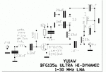
 

Attachments

  • AW_1-30M_BFG135a sch.gif
    AW_1-30M_BFG135a sch.gif
    20.1 KB · Views: 128
  • BFG135A.pdf
    100.6 KB · Views: 108

Here's your spice model. Maybe if you knew how to do an internet search you could have spent 30 seconds and found it, too!

Thanks for the link.
But what is an s2p file, this is not an ltspice file?
And I said Infineon not NXP, there are differences between the 2 devices. Read the question carefully please.
 

And I said Infineon not NXP, there are differences between the 2 devices. Read the question carefully please.
BFG135A has been discontinued by Infoneon more than 10 years ago. Be happy if you find a SPICE model of this or a similar transistor at all.

If the NXP model is s2p (table of s-parameters) it can't be used in SPICE simulator. According to discussions in LTspice user group, there has been at least a SPICE model of the Philips/NXP type available.
--- Updated ---

It's a BFR134A model with a package subcircuit
 
Last edited:

BFG135A has been discontinued by Infoneon more than 10 years ago. Be happy if you find a SPICE model of this or a similar transistor at all.

If the NXP model is s2p (table of s-parameters) it can't be used in SPICE simulator. According to discussions in LTspice user group, there has been at least a SPICE model of the Philips/NXP type available.
--- Updated ---

It's a BFR134A model with a package subcircuit
All right, thanks.
I think this will do, I have not tested it yet
**broken link removed**
--- Updated ---

All right, thanks.
I think this will do, I have not tested it yet
**broken link removed**
I imported it but it has some zero values. Should I worry on it?
 

Attachments

  • Capture.JPG
    Capture.JPG
    18.4 KB · Views: 108
Last edited:

I wouldn't worry about the Vceo and Ic parameters, those are max ratings for the device which aren't relevant for simulation purposes. Most third party models won't define them, which results in LTspice displaying them as zero.
 

    neazoi

    Points: 2
    Helpful Answer Positive Rating
I wouldn't worry about the Vceo and Ic parameters, those are max ratings for the device which aren't relevant for simulation purposes. Most third party models won't define them, which results in LTspice displaying them as zero.
Thanks very much for this information, it is goot to know.

But if you measure the collector currents on LTSPICE and they exceed the Ic of the device, then you do have a problem don't you? So at your final design you should check if the collector currents are exceeded.
Do I get this right?
 

But if you measure the collector currents on LTSPICE and they exceed the Ic of the device, then you do have a problem don't you?
Yes.
Most SPICE simulators do not monitor the maximum current or voltage ratings of devices, so it's up to you to determine that they remain below the device limits
 

    neazoi

    Points: 2
    Helpful Answer Positive Rating
Here is the LTspice model for BFG135 which I am using (is from NXP and not from Siemens as the one above):

.model BFG135 NPN(IS = 6.26489E-015 BF = 1.42485E+002 NF = 1.00616E+000 VAF = 4.48500E+001 IKF = 4.47193E+000 ISE = 3.79274E-013 NE = 2.07719E+000 BR = 9.14350E+000 NR = 1.05535E+000 VAR = 3.00000E+000 IKR = 3.62503E-002 ISC = 8.32089E-017 NC = 1.03925E+000 RB = 4.00000E+000 IRB = 1.00000E-006 RBM = 4.00000E+000 RE = 1.19858E+000 RC = 1.00000E+000 EG = 1.11000E+000 XTI = 3.00000E+000 CJE = 6.93680E-012 VJE = 6.00000E-001 MJE = 4.07326E-001 TF = 1.11019E-011 XTF = 5.41522E+001 VTF = 5.75002E+000 ITF = 9.98036E-001 PTF = 0.0000 CJC = 2.17679E-012 VJC = 2.78142E-001 MJC = 1.72323E-001 mfg=NXP)
 

    neazoi

    Points: 2
    Helpful Answer Positive Rating
LTSPICE is not an appropriate simulator for RF Circuits.I suggest you to use QUCS for that kind of RF Experiments.
Also, your circuit is not so good, Gain Deviation is huge.
S Parameter Plot 1.png
 
Last edited:

    neazoi

    Points: 2
    Helpful Answer Positive Rating
Thanks all!
My BFR92 RF amplifier collector current is like shown. From the datasheet, the Ic (DC) for the device is 25mA. But the collector current here varies from 8mA to 21.5mA (AC).

Would this be safe for the device (as the average current is lower) or not?
 

Attachments

  • Capture.JPG
    Capture.JPG
    51.5 KB · Views: 113

Status
Not open for further replies.

Part and Inventory Search

Welcome to EDABoard.com

Sponsor

Back
Top