shibas
Newbie level 6

- Joined
- Feb 13, 2013
- Messages
- 12
- Helped
- 0
- Reputation
- 0
- Reaction score
- 0
- Trophy points
- 1,281
- Activity points
- 1,393
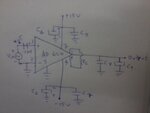
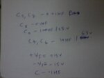
Iam posting my circuit diagram of the Ad 620 instrumentation amplifier and the values of components used in the circuit in two separate attachments.please refer to it and mention any change if i have to make to the circuit to get the amplified output.When i connected this circuit first i was not getting the required gain.But now iam getting very huge gain than the gain that is required.The gain equation for ad 620 is G=(49.4k/rg)+1. isn't it? I need a gain of about 100 or below 100.please help me.I used the 0.1 uf capacitor between the input signal and the non inverting input to remove the dc offset components.Is that correct to use it?
Do i need to insert a resistor between the inverting and non inverting input terminals of the op amp and ground that resistor to reduce the effect of the input bias current?
Some body please help me.
If the circuit diagram is wrong somebody please reply or upload a correct circuit diagram of the instrumentation amplifier using ad 620 ic.


