Continue to Site

Welcome to EDAboard.com

Welcome to our site! EDAboard.com is an international Electronics Discussion Forum focused on EDA software, circuits, schematics, books, theory, papers, asic, pld, 8051, DSP, Network, RF, Analog Design, PCB, Service Manuals... and a whole lot more! To participate you need to register. Registration is free. Click here to register now.

[SOLVED] Please Explain this Induced Voltage Waveform

Status
Not open for further replies.

hshah8970

Full Member level 2
Joined
Sep 17, 2011
Messages
144
Helped
18
Reputation
36
Reaction score
18
Trophy points
1,308
Activity points
2,385
Hello everyone.

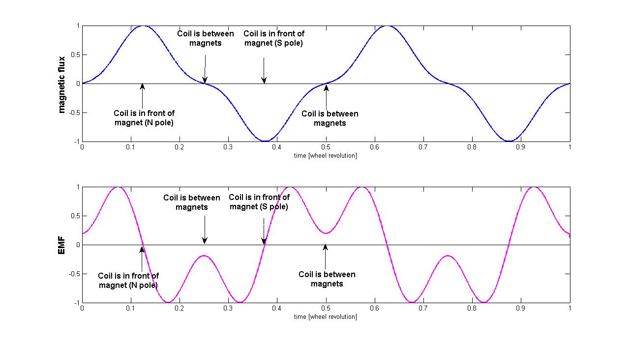
I'm inducing voltage into a coil using 4 magnets that are arranged circularly with alternating poles. You can see from the diagram that when the magnets are moved, EMF is induced into the coil.

I was expecting to see a sine wave produced in the coil but the waveform shown is quite different. Can somebody please offer an explanation?

Humza.

IMG_3113.jpg

IMG_3118.jpg
 

Hi Humza,

Taking into account that the induced EMF is proportonal to the time derivative of the magnetic flux across the winding, the shape of the flux that gives origin to the shown waveform should resemble a sinusoid with exagerated peaks and slow variations near the zero-crossings.
Let me explain: the waveform in your image is like a sinusoid plus a third harmonic with peaks in opposition, approximately A*[sin(wt)+0.75*sin(3wt)].
This correspond to the derivative of -A/w*[cos(wt)+0.25*cos(3wt)] (a sinusoid plus a third harmonic with coincident peaks). With a different delay, it is B*[sin(wt)-0.25*sin(3wt)].
It is very plausible that the waveform of the flux has this shape.
Note that the derivative emphasizes the high-frequency component.
I would expect that reducing the distance from the center of the disk to the megnets you could get a more sinusoidal waveform.
Regards

Z
 
Your setup resembles a motor. Motors have their own baffling combination of forces, both electrical and magnetic.

There are factors such as:

* a coil's reaction to its own magnetism, or to magnetism induced in the core, or any nearby metal (is your wire wound on a plastic or metal reel?)

* back-emf developing in windings as they move past a magnet

* size and shape of the coil, versus size and shape of the magnet

* shape of waveforms at a near approach of magnet to inductor

* where attractive force ends and repulsive force begins.

Example, a magnet approaches the coil. It generates an increasingly strong current as it gets closer (which you expect). Then the magnet travels past the empty space in the middle of your coil. What current is it generating at that point? Could that be the dip you observe?

---------------

Edited to add:

Now I realize your setup is really a generator rather than a motor. Nevertheless the two have similar forces at work and they have similar challenges.
 
Last edited:

I won't expect a sine wave anyway. But the folded-down waveform top demands for explanation.

Three aditional points:
- field orientation of the coin magnets, are you sure it's axial?
- disk material, is it steel?
- field orientation of the magnets among each other, all equal or alternating?
 

I brought the coil closer to the magnets and got a more sine-like wave; showing the comparison of BEFORE and AFTER in the following images. I cannot bring the coils any nearer otherwise I'm positive a better sine-like wave would've been achieved.

Are harmonics an explanation for this behavior?

Humza.

comparison.jpg
 

@BradTheRad:

Your explanation sounds like the best one. The waveform you see is a result of the disc moving at nearly 1200 revolutions per minute. Since each revolution makes the coil go through two pairs of magnetic poles, the frequency of the waveform should be twice i.e. 2400 rpm. Or 40 Hz, making the period 25 ms which is approximately what the waveform confirms.

Thanks for all the help everyone!
 

Isn't it that the zero crossings occur when the magnet is passing the coil center? And the said "two peaks per approach" have opposite sign?
 
@FvM:

I believe the zero crossing occurs when the coil is in the center of two magnets - just about to change from one magnetic pole to another. The absolute maximum and minimums occur when the magnets are right in front of the coil rims and the secondary maxima and minima we see are a result of the magnets being in the center of the coil.
 

I hope that the following plots can calrify my previous post (#2).
The plot swows a whole revolution of the wheel. Four magnets pass in front of the coil with alternate poles.
The second plot is the observed waveform (emf), that is proportional to the derivative of the first plot (effective magnetic flux crossing the coil).


Regards

Z
 
I have done some experimenting with real components. I can duplicate the waveform, but it requires more than a single magnet.

I find it requires that two magnets at opposite poles go past the coil (as the OP set up).

FvM is correct. A pass by a single magnet pole produces peaks at opposite polarity. The size of the coil does not matter.

My post #6 is misleading. I have added a caption for clarification:

35_1346557966.gif


I tried a narrow coil and a wide coil. I moved a magnet in various ways past the coil windings. Different distances. Different directions.

I moved the magnet toward the center and then held it stationary. I moved it away from the center.

I moved it over a rim and held it stationary. I moved it away from the rim. In various directions.

To sum up, there are 3 waveforms, as shown:

25_1346558293.gif


It follows the Right Hand Rule for Generators.

As for moving two magnets past the coil, this is the result:

76_1346559242.gif


I believe the opposite poles interact, even across a couple of inches. This is possible with today's super-strong magnets.

The negative waveform apparently gets cancelled out. The explanation is no doubt complicated.
 
It seems I had misunderstood your explanation, BradtheRad. Thanks for clarifying and thank you, FvM, for helping with the clarification.

Zorro, I immensely appreciate the wave plots. I hope it's alright if I use it in my project report to explain the wave.

Humza
 

Status
Not open for further replies.

Part and Inventory Search

Welcome to EDABoard.com

Sponsor

Back
Top