Continue to Site

Welcome to EDAboard.com

Welcome to our site! EDAboard.com is an international Electronics Discussion Forum focused on EDA software, circuits, schematics, books, theory, papers, asic, pld, 8051, DSP, Network, RF, Analog Design, PCB, Service Manuals... and a whole lot more! To participate you need to register. Registration is free. Click here to register now.

[SOLVED] piezoelectric transducer impedance matching

Status
Not open for further replies.

xeratule

Member level 4
Joined
Apr 4, 2009
Messages
69
Helped
1
Reputation
2
Reaction score
1
Trophy points
1,288
Location
Istanbul / TURKIYE
Activity points
1,975
Hi all,

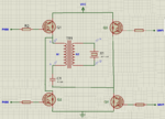
I am designing a driver board to drive piezoelectric crystal (ultrasonic) transducer sensor. I have a well operationg full bridge driver circuit which is driven by 25khz pwm (25khz is the resonance frequency of the transducer). I built a simplified circuit to focus on my problem, please see the attached file:

High power is flowing through high power IGBT while it is triggered by 25khz pwm. The driver circuit is connected to the primary side (N1) of a transformer. Secondary side of the transformer is connected to the transducer (crystal). I'm trying to have maximum active power from the transducer. When I measure the transducer output with impedance analyzer (disconnected from the circuit), at minimum impedance level it seems like 18nf capacitor which has about Xc = 1/ (2*pi*25000hz*18nf) = 350 ohms impedance. So should I have a transformer secondary side which has 350 ohms impedance XL = 2*pi*25000hz*L = 350 ohms which results in L=2.2uH. And If we look at the primary side of the transformer. I have 100nf of capacitor series to it. Should I also keep this side at resonance at 25khz? Xc = X(100nf) = XL(primary)? I think at resonance the reactive power is minimal and active power is at highest value. I am new to resonance and reactive loads so please help me to have an appealing and clear vision.

I actually tried some versions of transformer but couldn't get satisifying results. Sometimes got too few output current, sometimes transformer got too much temprature rise, sometimes got too many output current with unsatisifying power from the transducer.

Welcome to all replies, thanks in advance.

Erhan
 

Attachments

  • reactive load.png
    reactive load.png
    61.4 KB · Views: 253
Last edited:

A half bridge or push-pull driver to the transformer would be far more efficient than the single ended circuit you have shown - also it appears that the cap C1 will eventually charge up to the DC rail - after which there will be very little volts applied to the transformer when you turn Q1 on.
If you must use single ended, Q1 source/emitter should go to ground and put the transformer in the drain/collector and hook the remaining end of the transformer to Vcc (chuck away the 100n cap C1).
This way the drain of Q1 can go high during its off time allowing reset of the transformer flux, keep the duty cycle below 50%.
Regards, Orson Cart.
 
The circuit doesn't work, because there's no DC path for the IGBT current. Also the IGBT driver details are questionable, and you most likely would want a means to protect the IGBT against overvoltages.

Regarding impedance matching, I would ask at first for applicable voltage respectively power levels. What's the transducer specification? Usually, piezo transducers have an impedance characteristic similar to a crystal, showing adjacent parallel and series resonances. The impedance will be real at both of them, so you don't necessarily need a parallel inductor, although it's used in some applications.

Did you actually sweep the frequency through resonance? Otherwise the measurement would be useless. If 350 ohm is the real impedance determined in series resonance, then it can be used to calculate an impedance matching.
 

Dear Orson,

If you look carefully, I actually have a push pull full bridge circuit.
... I have a well operationg full bridge driver circuit which is driven by 25khz pwm (25khz is the resonance frequency of the transducer). I built a simplified circuit to focus on my problem, please see the attached file ...
I just scribbled down a quick and clear (obviously not, sorry) circuit to focus on. Hence you're right, I should have changed the IGBT position ... Anyway, I think my real problem is about impedance matching.... Btw I didn't understand what you meaned to chack away C1. Do you mean there should be no series capacitor to the primary winding of the transformer although assuming the circuit is corrected? I whink that series capacitor is necessary, as I see changing its value and that way loosing resonance at primary side leads to few power at output.
 

If you look carefully, I actually have a push pull full bridge circuit.
I'm sure, we looked carefully. Please don't foul us.

I see, you are just up to replace your schematic. :lol:
 

Dear FvM;

I'm sure, we looked carefully. Please don't foul us.
I see, you are just up to replace your schematic. :lol:
Yes I updated the schematic to full bridge view ... Sorry for misunderstandings ... I was just a little lazy to draw full schematic and to be clear I draw a simple schematic. Please see the updated attachment in my first post. Circuit PWM is operating in complementary pwm mode so that Q1&Q4 operates at one half Q2&Q3 at second half ...
-------

The circuit doesn't work, because there's no DC path for the IGBT current. Also the IGBT driver details are questionable, and you most likely would want a means to protect the IGBT against overvoltages.
.
Anyway, please don't stick into circuit DC path, driver circuit ... vs problems because the circuit actually operates good but not well enough to have maximum output power.
-----

Regarding impedance matching, I would ask at first for applicable voltage respectively power levels. What's the transducer specification? Usually, piezo transducers have an impedance characteristic similar to a crystal, showing adjacent parallel and series resonances. The impedance will be real at both of them, so you don't necessarily need a parallel inductor, although it's used in some applications.
Vcc = 220V, Transducer is capable of handling 300watts of output power. Yes, transducer may have adjacent parallel and series resonances but not have a real impedance at all. When I sweep the frequency between 24khz - 30khz it has a quite variable impedance though remaining between this range. And transducer's resonance frequency (minimum impedance frequency) changes with load and temprature. I thought if I design my circuit at resonance frequency where transducer impedance is least, I could get most power from it.

Erhan
 

Btw I didn't understand what you meaned to chack away C1. Do you mean there should be no series capacitor to the primary winding of the transformer although assuming the circuit is corrected? I whink that series capacitor is necessary, as I see changing its value and that way loosing resonance at primary side leads to few power at output.

All the resonance you need you can get from the leakage of the transformer and your load (you may need a cap in parallel on the sec side) having a series cap on the primary for a single ended drive (1 x transistor) simply will not work, hence chuck C1 away for that circuit as you need to let the collector volts rise to nearly 2 x the input volts to balance the volt-seconds applied to the transformer and get proper (resonant) operation.

Very similar to the single ended class AB drive of an audio stage or the class C drive of an RF stage, regards Orson Cart.
 

All the resonance you need you can get from the leakage of the transformer and your load (you may need a cap in parallel on the sec side) having a series cap on the primary for a single ended drive (1 x transistor) simply will not work, hence chuck C1 away for that circuit as you need to let the collector volts rise to nearly 2 x the input volts to balance the volt-seconds applied to the transformer and get proper (resonant) operation.
.

I operated the circuit (4 IGBT's full bridge push pull circuit) both with cap C1 and without it (while keeping the supply voltage same for each). I can get more current drain and active power when I apply the capacitor.

On the other hand if I apply a parallel capacitor to the crystal (secondary side) far bigger than the capacitive effect of the crystal (1uf to 20nf respectively) that creates a stable capacitive effect to match and keep the load close to resonance but will create nearly a short circuit (as pwm is AC) and most of the current will flow through that capacitor. I can't figure out the advantage of a parallel capacitor.
 

C1 is required for full bridge but does not work for single ended. Have you considered extra L on the sec side (or a xfmr with increased leakage) to help you obtain a nicer resonant operation?
Regards, Orson Cart.
 

Yes, transducer may have adjacent parallel and series resonances but not have a real impedance at all.
Would be the first transducer that hasn't a real impedance at resonance frequency. But you didn't show the impedance measurement. Normally, the impedance will be inductive at one side of a resonance and capacitive at the other, applies both to series and parallel resonance.

Better results with the 100 nF capacitor can be expected, if the transformer has considerable leakage inductance. For an exact calculation, it's best to measure the transformer parameters.
 

Would be the first transducer that hasn't a real impedance at resonance frequency. But you didn't show the impedance measurement. Normally, the impedance will be inductive at one side of a resonance and capacitive at the other, applies both to series and parallel resonance..
Transducer of course has real impedance,what I tried to explain was it's not purely resistive at all, sorry about my english :( ...

Have you considered extra L on the sec side (or a xfmr with increased leakage) to help you obtain a nicer resonant operation?
.
I tried many different transformers, different windings for both primary and secondary side. Actually I don't know how leakage inductance is used and controlled.
Please answer these questions that confuses me alot:

I have a piezoelectric transducer where its minimum impedance (Zmin) and frequency of Zmin changes with variable loads applied on it. Temprature change also effects them too. What I try to do is to have maximum active output power (capable of doing work) from transducer.

1) P = V*I ... Let Vcc = 150V. Pmax = 300W for transducer. So it is capable of handling 2A of currents?
Is the power formula above applies for PWM too? I have %50 duty cycle push pull full bridge circuit. I mean half of the time Q1&Q4 active, and at the other half Q2&Q3 (please see attached file in my first post). So can I apply more current than 2A?

2) When will I have most active power from the transducer? How can I measure active power at that point without wattmeter?
a) Is it when (at frequency where) the (Z) impedance is minimum? At this frequency point theta is below zero which shows capacitive effect. Should I match this value with transformer secondary at this frequency?
b) Is it when the (theta) phase angle is 0 (Z is all resistive)? At this frequency point Z = R but has a value of much higher impedance than Zmin. Should I use this value and omit all impedance matching components (transformer, capacitor)?
c) Is it somewhere else or maybe I am completely on wrong way? ( Oh man I really got confused :( )

3) Should I adjust transformer secondary side impedance to resonate with the transducer at one of above frequencies? Which one?

Please help me to overcome these blur ideas on my mind. Some of them may be very elementary but I couldn't get out of this complicated situation.

Thanks in advance
 
Last edited:

The frequency that will give you the most real power transfer at a given drive voltage is the resonance that has the lowest real impedance. For piezo elements this resonance usually has a significant capacitive reactance that you want to tune out, usually with a series inductor on the secondary side of the transformer. Your series capacitor C1 is working against you for tuning. If you make C1 real big so that its reactance is negligable it may prevent damage in the case of drive failure. But it does not help tune the ducer.

Use your impedance analyser to find the frequency with lowest real impedance. Find the capacitive reactance at that frequency. Wind a series inductor to tune out that reactance. Now measure the real impedance of the ducer inductor combination. It should be a low, fairly resistive value. Now make your transformer to drive the power you want into the resistive load you have from the voltage you have. Usually you can use the same core for the inductor as for the transformer, but add a gap to the inductor core.

It is possible to gap the transformer core and have it do double duty, but that is only for advanced students that have mastered the two core method first.
 
If you're going to make a dual resonant drive circuit like this, then you will want to ensure that you see zero current switching on the output of your IGBTs. That will dramatically increase efficiency and ensure maximum power transformer (though be careful that the power actually goes into the piezo, instead of just resonating in the primary circuit without coupling to the secondary).
 

The frequency that will give you the most real power transfer at a given drive voltage is the resonance that has the lowest real impedance. For piezo elements this resonance usually has a significant capacitive reactance that you want to tune out, usually with a series inductor on the secondary side of the transformer. Your series capacitor C1 is working against you for tuning. If you make C1 real big so that its reactance is negligable it may prevent damage in the case of drive failure. But it does not help tune the ducer.
Wouldn't transformer secondary do the tuning or an effect on tuning? Why should I additionally use series inductor?
Yes, C1 is not for tuning and is effective to neglect mutual inductance effect. And I'm not sure but it is said to soften the PWM edges and thus helps the transformer heat less. It is a small value like 100nf in this application.
 

If it was an ideal transformer, with perfect coupling, no losses or leakage etc., the transformer would have no affect on tuning. With modern cores and good winding practice you can get pretty close to an ideal transformer, or an ideal inductor. Solving one equation at a time is easy. By gapping and shunting the transformer you can get it to do both functions at once, but the engineering calculations and manufacturing tollerances get very difficult. It depends on costs and volume. If you are only building a few hundred of something it is not generally worth the effort to get the single core solution to work. If you are building 100,000's of units, and can spend the engineering time and materials for scrap test units, or it is for a satellite where weight rules and costs be dammed, it may be worth it in the end. But even in that case you will still want to build the two core solution first to get the test data you will need for the single core solution.
 
Status
Not open for further replies.

Similar threads

Part and Inventory Search

Welcome to EDABoard.com

Sponsor

Back
Top