Continue to Site

Welcome to EDAboard.com

Welcome to our site! EDAboard.com is an international Electronics Discussion Forum focused on EDA software, circuits, schematics, books, theory, papers, asic, pld, 8051, DSP, Network, RF, Analog Design, PCB, Service Manuals... and a whole lot more! To participate you need to register. Registration is free. Click here to register now.

PICmicro current consumption

Status
Not open for further replies.

me_guitarist

Full Member level 6
Joined
Oct 3, 2006
Messages
338
Helped
0
Reputation
0
Reaction score
0
Trophy points
16
Location
Malaysia
Activity points
0
Hello everyone,

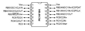
I'm using PIC16F506 with thermistor to do some ADC measurements.
Currently using internal 4MHz oscillator on 5VDC & operating current around 1mA.
How do I reduce the current, let say below 100uA?

Will a low power crystal like 32.768kHz reduce the operating current?
Any other way beside entering sleep mode to conserve current?
or the thermistor consume too much current?

Pls help & thanks in advance!
 

Lowering the oscillator frequency will certainly reduce current consumption at expense of computation power.

There is trade off between the two, so decide accordingly.
 

or the thermistor consume too much current?
How can we know, if you don't show the circuit? But I would simply assume, that it's meaningful to supply the respective circuit only during measurements.

Generally, you can achieve minimal current consumption with INTOSC and sleep. You have to think also about suitable settings for various internal resources.
 

thanks for yr reply guys!

my circuit:

a 100k NTC thermistor connected to pin 13 of 16F506 & tied to GND, a 4k3 resistor connected to pin 13 & tied to VDD (like a voltage divider) & an LED connected to pin 7. Thats all.

one more thing, can ADC wake the mcu from sleep like comparator?

Thanks!
 

31_1258977462.jpg


I only use pin 13 for ADC & comparator to set programmable threshold voltage, 1 LED output on RC3.
MCLRE enabled & pulled-up with 10K resistor.
What should I do with the rest of pins 2,3,5,6,8~12?

As I know it need to be configure as input & tied to VDD or VSS.
If I enable comparator 2 & use C1IN+ as input, what should I do with pin 6,8,9,10?
Can I still able to configure those unused pins as input & tie to VSS?

Thanks for yr help!
 

You have two choices:

1. Make the pins inputs in which case they have high impedance and need either pull-up or pull-down resistors to minimize the risk of static damage or the pin randomly being seen as high and low which might increase current consumption.

or

2. Make the pins outputs and do not connect them externally at all. The driver circuit behind the pin will sink or source any pickup on the pin and keep it at a safe voltage.

Note that 2 requires no external components but does have a slight disadvantage over 1, that being that when the power is removed, the pin will float again and become susceptible to static damage.

It's your choice but I wouldn't just ignore the pins or tie them directly to the supply or ground.

Brian.
 

Hi Brian,

Thanks for yr advice.
I configured all the unused pins as input & tied them to VDD or VSS (which is convenient) still drawn some current if enter sleep mode.

Maybe some code error?
I'll have a check again on my code.

by the way, how can we drawn below 200uA while the ADC module is active?

The best I can do is running at 3VDC with 450uA.

Thanks!
 

I'm under the impression, that you didn't yet check the exact current consumption of various peripheral functions, e.g. ADC
respectively didn't think thoroughly about a useful operation mode of your device.

In my opinion, it's obvious, that a slow varying analog signal, e.g. a temperature, wouldn't be monitored by a permanently
enabled ADC. My comment about supplying resources during measurements is also valid for internal resources. For
minimum current resources, use the watchdog as the only permanently enabled function. That's, what everyone does.
 

Thanks Fvm.

I'm using WDT to periodically wake-up from sleep & measure the input then compare the results, the program will only continues to run if there was a increment in temperature, else it will enter sleep mode again & wait for the watchdog to time out.

how can I calculate the threshold value for ADC?
I'm using 100K NTC thermistor connect from PIN 13 to VDD, a 50K resistor from pin 13 to GND.

let say if I want to turn on an LED if temperature overed 50C. what value (0~255) I need to subtract ?
 

NTC have rather exactly defined characteristics, that can be found in the datasheet. But different NTC have different T.C. (respectively "B" value). You can expect between 30 and 50 % of nominal 25° resistance at 50°, so the ADC code may vary between about 128 and 160 in your circuit for different NTC types.
 

FvM said:
NTC have rather exactly defined characteristics, that can be found in the datasheet. But different NTC have different T.C. (respectively "B" value). You can expect between 30 and 50 % of nominal 25° resistance at 50°, so the ADC code may vary between about 128 and 160 in your circuit for different NTC types.

Thanks FvM.

I configured a pin to input but didn't use this pin at all. Do I need to connect an external pull-up resistor or the internal pull-up will do?
 

Status
Not open for further replies.

Similar threads

Part and Inventory Search

Welcome to EDABoard.com

Sponsor

Back
Top