ksay2k
Newbie level 4
DIY pickit2 clone problems
Hello everyone.
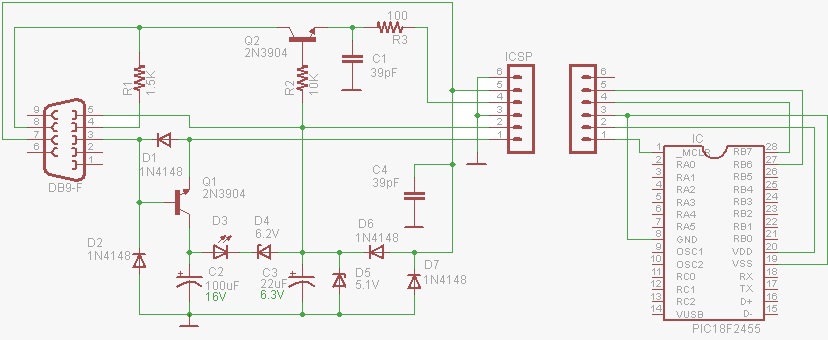
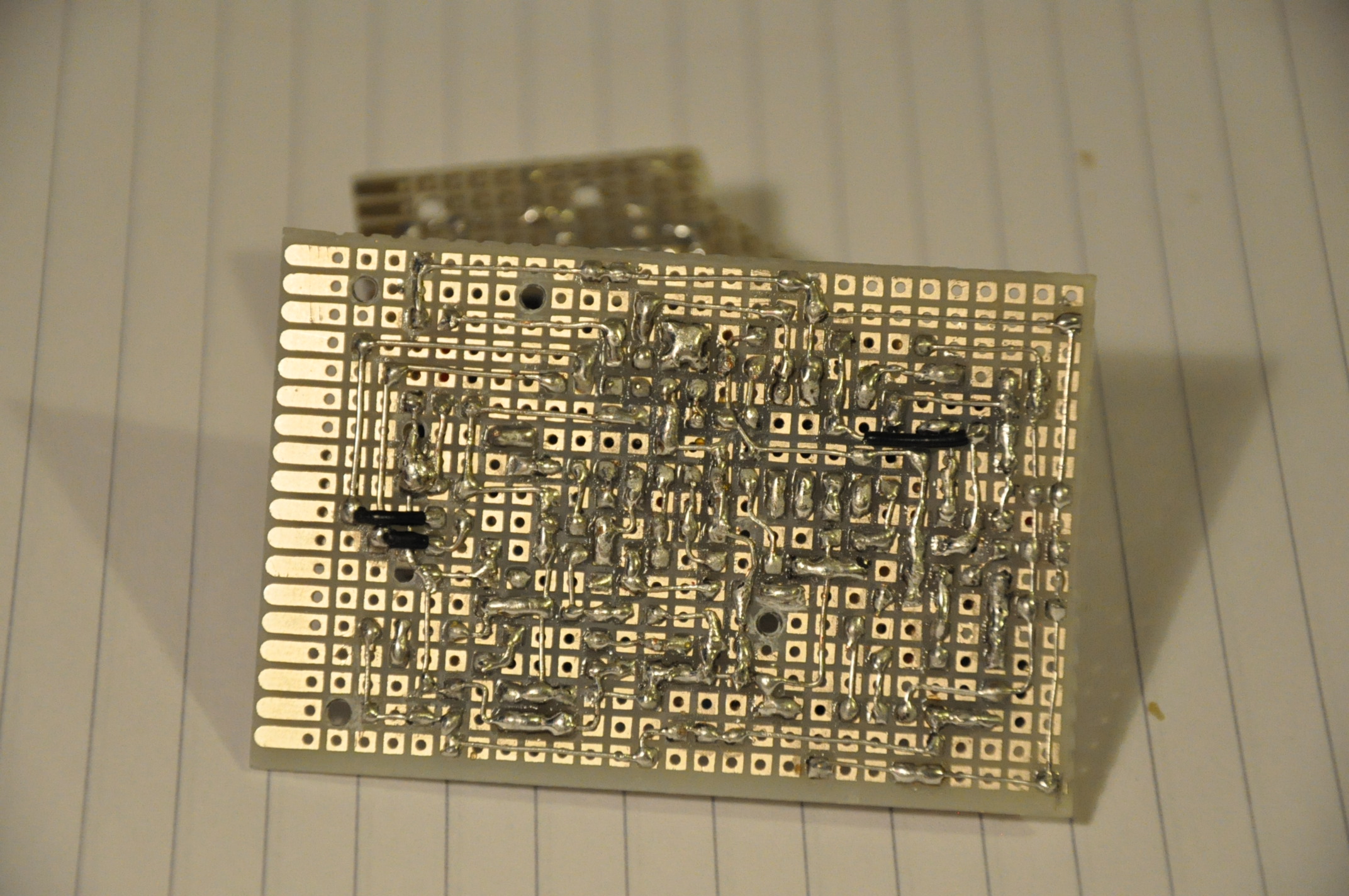
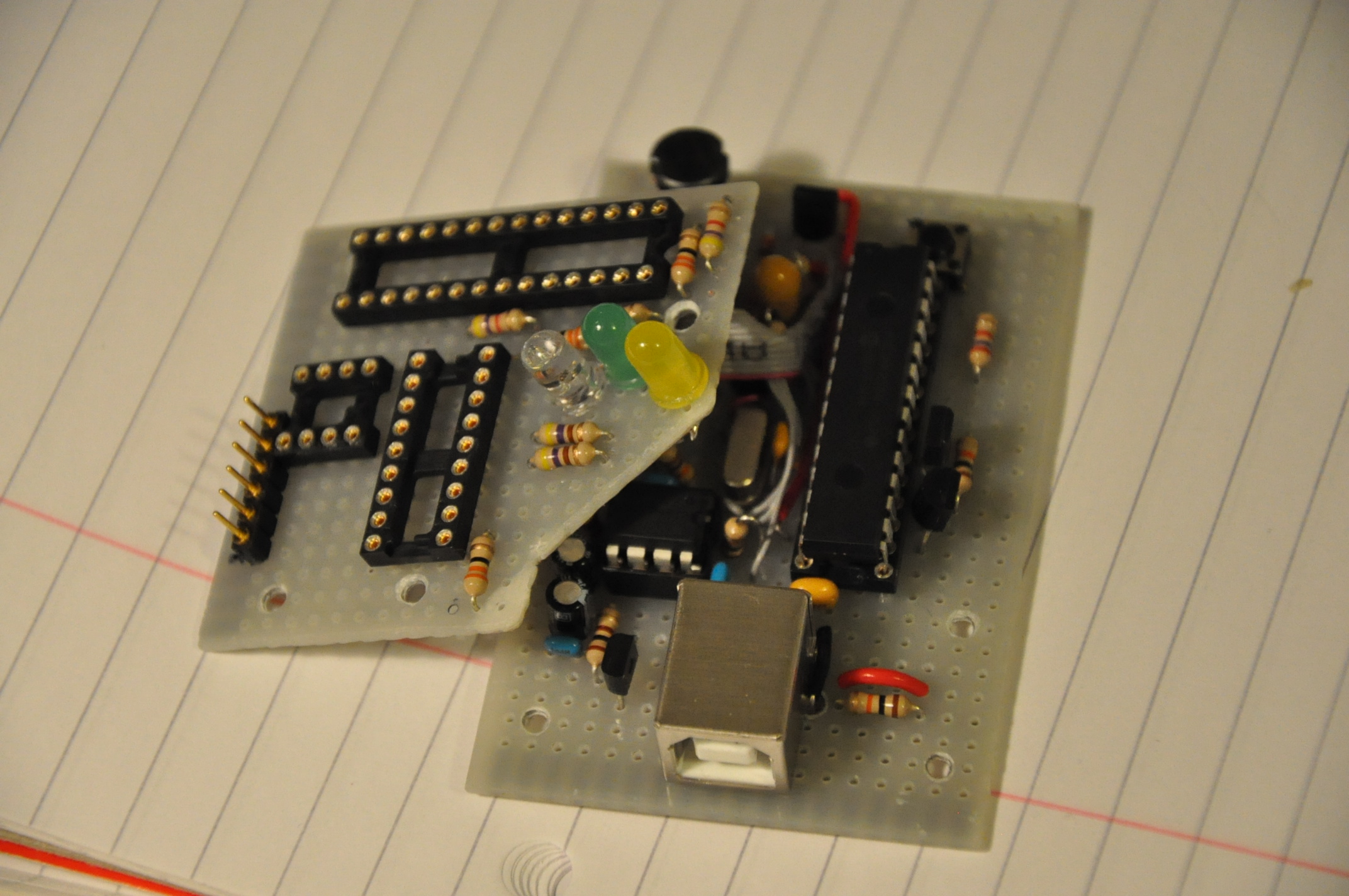
I`m a just Pickit-beginner. I actually built DIY PICKIT2 clone as followed a circuit schematic on Programming PIC18F
And I also built JDM2 programmer due to an egg-chick problem on that clone, source from JDM2 PIC 18F Programmer
I spent whole week with them and am almost crying now because it is not working properly. I need some helps from you, experts.
Firstly, the bootloader to start clone, PIC18f2550 was programmed by PK2V023200.hex. I tried this hex file in several times with JDM2 and PICPGM software but when it is verified it came up something like "Verify error occufied " then exit automatically.
If I want to solve this problem, do I have to madify something on the JDM2 circuit ?
Second, I tried another hex file ,PK2V023201.hex. This was worked well with JDM programmer as successfully. Then I put pic18f2550 chip into PICKIT2 clone that I built and connected to USB-com. However, my laptop did not read my CLONE, looks like a problem of compatibility, I think.
To figure this out, I checked the home made-clone circuit so many times whether it is soldered right but it seems ok.
I still do not know what the problems are.................
is the problem home made-clone circuit? or voltage supply? or software?
Please help me.... give me some clues....
Thank you,
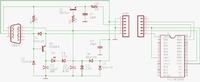
I`ll leave the schematics I used.

Hello everyone.
I`m a just Pickit-beginner. I actually built DIY PICKIT2 clone as followed a circuit schematic on Programming PIC18F
And I also built JDM2 programmer due to an egg-chick problem on that clone, source from JDM2 PIC 18F Programmer
I spent whole week with them and am almost crying now because it is not working properly. I need some helps from you, experts.
Firstly, the bootloader to start clone, PIC18f2550 was programmed by PK2V023200.hex. I tried this hex file in several times with JDM2 and PICPGM software but when it is verified it came up something like "Verify error occufied " then exit automatically.
If I want to solve this problem, do I have to madify something on the JDM2 circuit ?
Second, I tried another hex file ,PK2V023201.hex. This was worked well with JDM programmer as successfully. Then I put pic18f2550 chip into PICKIT2 clone that I built and connected to USB-com. However, my laptop did not read my CLONE, looks like a problem of compatibility, I think.
To figure this out, I checked the home made-clone circuit so many times whether it is soldered right but it seems ok.
I still do not know what the problems are.................
is the problem home made-clone circuit? or voltage supply? or software?
Please help me.... give me some clues....
Thank you,
I`ll leave the schematics I used.


")