bhoobalan
Member level 1
Hello friends,
I am new to this pic24fj128ga010 controller. In my project i want to use two pic24fj128ga010 controllers at a same time using UART communication. I have two Explorer 16 Boards, For Example i have taken that 1st board as Transmitter and 2nd board as Receiver. In the Transmitter i have Buttons and i Receiver i have Led's. Concept is that , when the button is pressed in the Transmitter and respective operation is done in Receiver Led.
I write the code for both transmitter and receiver and also i checked in Proteus simulation and it works fine. But in the hardware i did not get the out what i have already get from Proteus simulation.
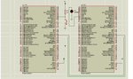
I have attached the code and the simulator connection image that i have made.
Please refer this code and let me know if there is any mistake. And tell me that what should i want to do for the out put in hardware?
I am waiting for the reply
Thanks in advance
I am new to this pic24fj128ga010 controller. In my project i want to use two pic24fj128ga010 controllers at a same time using UART communication. I have two Explorer 16 Boards, For Example i have taken that 1st board as Transmitter and 2nd board as Receiver. In the Transmitter i have Buttons and i Receiver i have Led's. Concept is that , when the button is pressed in the Transmitter and respective operation is done in Receiver Led.
I write the code for both transmitter and receiver and also i checked in Proteus simulation and it works fine. But in the hardware i did not get the out what i have already get from Proteus simulation.
I have attached the code and the simulator connection image that i have made.
Please refer this code and let me know if there is any mistake. And tell me that what should i want to do for the out put in hardware?
I am waiting for the reply
Thanks in advance