Continue to Site

Welcome to EDAboard.com

Welcome to our site! EDAboard.com is an international Electronics Discussion Forum focused on EDA software, circuits, schematics, books, theory, papers, asic, pld, 8051, DSP, Network, RF, Analog Design, PCB, Service Manuals... and a whole lot more! To participate you need to register. Registration is free. Click here to register now.

PIC18F4553 and bluetooth

Status
Not open for further replies.
this is my code I'm stuck in the adc part I'll explain what I do:

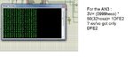
I have 7 analog channels to be converted:
AN0: need to be *4
AN1:
AN2:
AN3: need to be * 50
AN4: need to be * 50
AN5: need to be *4
AN6: need to be *4
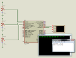
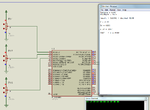
but in the simulation all channels are correct except for 50 ?? here is my code
Code:
unsigned char lowbyte;
unsigned char highbyte;
unsigned char medbyte;
unsigned int conversion1 ;
unsigned int TAB[24][7];
unsigned int conversion[12];

void main()
{
 int i= 0;

/////////Initialization//////////////////
ADCON1=0x03; //VSS,VDD, ALL ANi are analog except for AN12
ADCON0=0x01; //select AN0
ADCON0=0x05; //select AN1
ADCON0=0x09; //select AN2
ADCON0=0x0D; //select AN3
ADCON0=0x11; //select AN4
ADCON0=0x15; //select AN5
ADCON0=0x19; //select AN6
ADCON2=0xAD; //Right justified, 12TAD, 16TOSC
TRISA=0xFF; // set trisA as inputs
TRISE=0b1111; // set trisE as inputs

ADON_bit=1; // enable conversion
UART1_Init(9600); // Initialize hardware UART1 and establish communication at 9600 bps
Delay_ms(100); // Wait for UART module to stabilize
/////////ADC CONVERSION///////////////////
   while(1)
    {
        for( i=0 ;i<7;i++)
             {
                conversion[12] = ADC_Read(i); // Read analog value from channel 0 to 6

                if( i == 0 || i == 5 || i == 6)
                TAB[24][i]= conversion[12]*4;
                if( i == 3|| i == 4 )
                TAB[24][i]= conversion[12]*30;
                if( i ==1 || i == 2 )
                TAB[24][i]= conversion[12];

                lowbyte= TAB[24][i]>>16;
                medbyte = TAB[24][i]>> 8;
                highbyte= TAB[24][i];
                UART1_Write(lowbyte);
                UART1_Write(medbyte);
                UART1_Write(highbyte);

delay_100ms() ;

delay_100ms() ;

delay_100ms() ;

delay_100ms() ;

delay_100ms() ;

delay_100ms() ;

delay_100ms() ;

              }
       }
}


Code C - [expand]
1
2
3
4
5
6
7
8
9
10
11
12
13
14
15
16
17
18
19
20
21
22
23
24
25
26
27
28
29
30
31
32
33
34
35
36
37
38
39
40
41
42
43
44
45
46
47
48
49
50
51
52
53
54
55
56
57
58
59
60
61
62
63
64
65
66
67
68
#define LED1 RD1_bit        //LED1 connected to RD1
#define LED2 RD2_bit        //LED2 connected to RD2
#define Relay RD0_bit       //Relay connected to RD0
#define Buzzer PORTD.F7      //Buzzer connected to RD7
#define BTSense RC0_bit     //assuming GPIO2 of bluetooth is connected to input pin RC0 of uC
 
 
unsigned char lowbyte;
unsigned char highbyte;
]unsigned int result[7];
 
void main()
{
 int i= 0;
 
/////////Initialization//////////////////
  ADCON1=0x03;      //VSS,VDD, ALL ANi are analog except for AN12
  ADCON2=0xAD;      //Right justified,  12TAD, 16TOSC
  TRISA=0xFF;       // set trisA as inputs
  TRISE=0b1111;    // set trisE as inputs
  TRISD=0x00;
  TRISC=0b1011000;
  TRISE=0b111;
  TRISC = 0x81;
  PORTD = 0x00;
     
  Buzzer = 1;
  Delay_ms(3000);
  Buzzer = 0;
 
  
  UART1_Init(9600);     // Initialize hardware UART1 and establish communication at 9600 bps
  Delay_ms(100);        // Wait for UART module to stabilize
 
        while(1){
 
        if(BTSense)
        {
 
            LED1 = 1;
            Relay = 1;
 
        }
        else if(!BTSense)
        {
 
            LED1 = 0;
            Relay = 0;
            LED2 = 1;
        }
 
 
            for(i=0;i<7;i++)
            {
                 result[i] = ADC_Read(i);  // Read analog value from channel 0  to 6
                   
          if((i == 0) || ( i == 5) || (i == 6))result[i] = result[i] * 4;
          elseif((i == 3) || ( i == 4))result[i] = result[i] * 50;              
                  
                  lowbyte = result[i] & 0x0F;
                  highbyte = result[i] >> 8;
                  UART1_Write(lowbyte);
                  UART1_Write(highbyte);
                  
                  
             }
        }
}


thank you but it doesnt work. because i have for example for my input AN3 : 3V that corresponds to 0999 multiplied by 50 = i have to find 1DFE2 or for AN0 :2.5V corresponds to 07FF multiplied by 4 = 1FFC . when i simulate your code the result isnt correct in hyperterminal. (ADC of 12 bits)
 

My code is not wrong. Your code is wrong. Maybe your ADCON1 and ADCON2 settings are wrong. It your adc is 12 bits then for 5V you will get 4095. So for 3V it will be 2457.6. and 2457.6 * 50 = 122880.
 

yeah i know but in the code i sent you it works fine but not for channels that are multiplied by 50. I think ADCON1 and ADCON2 are correct.
 

Replace the line result = result & 0x0F; with result = result;
Add CVRCON.CVROE = 0;
TRISC = 0b10110000;

93408d1373455173-adcfix.png


You can also use

lowbyte = result & 0x00FF;;
 

Attachments

  • adcfix.png
    adcfix.png
    59 KB · Views: 77
Last edited:

see this :)

- - - Updated - - -

when its 2.5 V *4 =07FF*4=1FFC its okay u send highbyte then lowbyte we can see in hyperterminal FC1F
but for 3 V*50= 0999*50= 1DFE2 , in hypertminal its E2DF ? why is the other bytes not displayed ?
 

Attachments

  • problem1.jpg
    problem1.jpg
    127.5 KB · Views: 51

That is because 0x1DFE2 is > 0xFFFF (65535). unsigned int is 2 bytes (16-bits). unsigned int can only hold max of 65535. Use float instead.


Edit. You can use unsigned long instead of int.


Code C - [expand]
1
2
3
4
5
6
7
8
9
10
11
12
13
14
15
16
17
18
19
for(i=0;i<7;i++)
            {
                 result[i] = ADC_Read(i);  // Read analog value from channel 0  to 6
 
 
          if((i == 0) || ( i == 5) || (i == 6))result[i] = result[i] * 4;
          else if((i == 3) || ( i == 4))result[i] = result[i] * 50;
 
                  lowbyte = result[i] & 0x000000FF;;
                  highbyte = result[i] >> 8;
                  higherbyte = (result[i] & 0x00FF0000) >> 16;
                  highestbyte = (result[i] & 0xFF000000) >> 24;
                  UART1_Write(lowbyte);
                  UART1_Write(highbyte);
                  UART1_Write(higherbyte);
                  UART1_Write(highestbyte);
                  Delay_ms(1000);
 
             }


93413d1373460755-adcfix2.png
 

Attachments

  • adcfix2.png
    adcfix2.png
    85.3 KB · Views: 69
Last edited:

when i use float or double;
I've got an error
Code:
operator is not applicable to these operations
in lowbyte and highbyte
 

mmmmmm..okay . I tought that
Code:
lowbyte = result[i];
                  highbyte = result[i] >> 8;
are enough they do the same things as built in routines

- - - Updated - - -

how could i do that :s ?? I think im gonna need 3bytes.

- - - Updated - - -

how could i do that :s ?? I think im gonna need 3bytes.

- - - Updated - - -

you declare higherbyte and highestbyte as float?

- - - Updated - - -

thank you its working now sir :grin:
 

hello,

why are you using table for receiving ADC value (12 bits), a simple Integer is enough .
and for result after mutiplying, 24 bits are enough for the maximum result 4096*50 .. but better to use a long int (32bits)
Then you can isolate the 3 bytes LSB,MSB,HSB

so your code becomes :
Code:
unsigned char lowbyte;
unsigned char highbyte;
unsigned char medbyte;
//unsigned int TAB[24][7];
unsigned long  TAB[7];		// table for 7  values (32 bits)
//unsigned int conversion[12];
unsigned int conversion;	// integer 16 bits , enough for receiving ADC 12 bits long

void main()
{
 int i= 0;

/////////Initialization//////////////////
ADCON1=0x03; //VSS,VDD, ALL ANi are analog except for AN12
ADCON0=0x01; //select AN0
ADCON0=0x05; //select AN1
ADCON0=0x09; //select AN2
ADCON0=0x0D; //select AN3
ADCON0=0x11; //select AN4
ADCON0=0x15; //select AN5
ADCON0=0x19; //select AN6
ADCON2=0xAD; //Right justified, 12TAD, 16TOSC
TRISA=0xFF; // set trisA as inputs
TRISE=0b1111; // set trisE as inputs

ADON_bit=1; // enable conversion
UART1_Init(9600); // Initialize hardware UART1 and establish communication at 9600 bps
Delay_ms(100); // Wait for UART module to stabilize
/////////ADC CONVERSION///////////////////
   while(1)
    {
        for( i=0 ;i<7;i++)
             {
                conversion = ADC_Read(i); // Read analog value from channel 0 to 6

                if( i == 0 || i == 5 || i == 6)
                TAB[i]= (long) conversion *4;
                if( i == 3|| i == 4 )
                TAB[i]= (long) conversion*50;
                if( i ==1 || i == 2 )
                TAB[i]=(long) conversion;

                lowbyte= (unsigned char)(TAB[i] & 0x000000FF);
                medbyte = (unsigned char) ((TAB[i]>> 8) & 0x000000FF);
                highbyte= (unsigned char) ((TAB[i] >> 16) & 0x000000FF);
                UART1_Write(lowbyte);
                UART1_Write(medbyte);
                UART1_Write(highbyte);

delay_100ms() ;
delay_100ms() ;
delay_100ms() ;
delay_100ms() ;
delay_100ms() ;
delay_100ms() ;
delay_100ms() ;

              }
       }
}
 
lowbyte, highbyte, higherbyte, and highestbyte are all unsigned char (8 - bits) result is an array of unsigned long type which is 4-bytes wide. Why do you want to transmit bytes. You can do the necessary calculation on the raw adc value and then convert the result to string and then transmit it.
 

Hi everybody,

Thank you guys for your help :), sorry for being late for the reply.
I've told you before that I'm using a RN-42 bluetooth module and I'm trying to configure it (mode, baudrate..). I get inspired by this website( https://www.forward.com.au/pfod/Ard...uetooth (XBee format) module on FioV3|outline), which makes the configuration but with an arduino.

This is my code,
Code:
void main()
{
     /////////Initialization//////////////////
     TRISC=0b1011000;
     UART1_Init(9600);                           // Initialize hardware UART1 and establish communication at 9600 bps
     Delay_ms(100);                             // Wait for UART module to stabilize
      ////////Configuration////////////////////
      
         UART1_Write_Text("$$$");
         DELAY_MS(500);
         UART_Write_Text("SU,9600");            // Change the baudrate to 9600
         UART1_Write(0x09);                     // new line     NL
         UART1_Write(0x0d);                     // enter CR
         UART_Write_Text("R,1");                // Reboot
         UART1_Write(0x09);                     // new line     NL
         UART1_Write(0x0d);                     // enter CR
         UART1_Write_Text("$$$");
         DELAY_MS(500);
         UART1_Write(0x09);                     // new line     NL
         UART1_Write(0x0d);                     // enter CR
         UART_Write_Text("SM,0");               // Slave mode
         DELAY_MS(500);
         UART1_Write(0x09);                     // new line     NL
         UART1_Write(0x0d);                     // enter CR
         UART_Write_Text("SA,4");               // Authentification Pin code mode
         DELAY_MS(500);
         UART1_Write(0x09);                     // new line     NL
         UART1_Write(0x0d);                     // enter CR
         UART_Write_Text("SP,0000");            // Set Pin code to 0000
         DELAY_MS(500);
         UART1_Write(0x09);                     // new line     NL
         UART1_Write(0x0d);                     // enter CR
         UART_Write_Text("ST,0");               // Configuration timer, disable remote config
         DELAY_MS(500);
         UART1_Write(0x09);                     // new line     NL
         UART1_Write(0x0d);                     // enter CR
         UART_Write_Text("S~,0");               // Enable SPP protocol
         DELAY_MS(500);
         UART1_Write(0x09);                     // new line     NL
         UART1_Write(0x0d);                     // enter CR
         UART_Write_Text("D-");                 // Print the main settings to check
         DELAY_MS(500);
         UART1_Write(0x09);                     // new line     NL
         UART1_Write(0x0d);                     // enter CR
         UART_Write_Text("R,1");                // Reboot to apply settings
I wrote this code which work when I uncheck the box of TFT library but when its cheked it does not work.
 
Last edited:

If you are not using TFT in your project then you can uncheck TFT library. If you need TFT lib then reinstall mikroC.

UART_Write_Text("SU,9600"); // Change the baudrate to 9600
UART1_Write(0x09); // new line NL
UART1_Write(0x0d);

Is the above right? Or is it

UART_Write_Text("SU,9600"); // Change the baudrate to 9600
UART1_Write(0x0D); // new line NL
UART1_Write(0x0A);

??
 

Good morning,

Yes I unchecked it and it works fine without it. I join an image of what i found in mikroC manual.
nl&cr.jpg
 

Okay thank you. :-D

I have another problem to solve always in the same program of the PIC. I have a car battery voltage between 0 and 16 volts which I divide by 4 since the pic does not exceed 5 volts (this is why I needed to multiply by four to get the full information), I acquired the AN0 pin. I linked Vbattery with INT0. AND I want to scrutinize this tension if down over a Vthreshold = 2v) I retrigger the acquisition and I start again.

As we did before start acquisition -> conversion -> save and send through UART.i have to add the interruption scan. How could I do that?

See the attachment, battery voltage and the interruption in proteus.
Vbattery.jpg
 

I didn't understand what you are saying. What do you want to do? If INT0 is used to check if Battery is below 2V or some threshold and then start reading battery voltage if true. Then you can use any digital i/p pin for that. Use a Non-Inverting amplifier to amplify Battery 2V to 5V and this 5V will trigger INT0 pin (you can use interrupt). So it INT0 becomes high when Battery V is <=2V then you can set a flag in isr which will be tested in while(1) loop. If flag is true then adc is read i.e., data is acquired.

To help you better zip and post your mikroC files and Proteus file.
 

okay see your private message
 
Last edited:

Status
Not open for further replies.

Similar threads

Part and Inventory Search

Welcome to EDABoard.com

Sponsor

Back
Top