Continue to Site

Welcome to EDAboard.com

Welcome to our site! EDAboard.com is an international Electronics Discussion Forum focused on EDA software, circuits, schematics, books, theory, papers, asic, pld, 8051, DSP, Network, RF, Analog Design, PCB, Service Manuals... and a whole lot more! To participate you need to register. Registration is free. Click here to register now.

[SOLVED] pic18 not simulating in proteus

Status
Not open for further replies.

h.sharma

Junior Member level 3
Joined
Jun 16, 2012
Messages
30
Helped
1
Reputation
2
Reaction score
1
Trophy points
1,288
Activity points
1,455
hello everyone when I am simulating for pic18 mc in proteus it is not simulating expected, bt it is working perfect 4 pic16

my hex file is running perfect in pic simulator and also in debugging in mplab

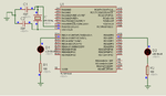
i am attaching my ckt simulating in proteus

there is no prob with proteus for pic16

plz tell me whats wrong with this ckt and how to simulate for pic18 in proteus

my code is
Code:
#include<p18f4550.h>
#include<delays.h>
int i,d;
#define us(d) for(i=0;i<d;i++){Delay1TCY();}
#define ms(d) for(i=0;i<d;i++){Delay1KTCY();}

void main(void){
TRISB=0x00;
TRISD=0X00;
while(1){
PORTB=0XFF;
PORTD=0XFF;
}
}
 

Attachments

  • 2.png
    2.png
    24.1 KB · Views: 67
Last edited:

One issue is that the PORT pins RB0:RB4 are configured as ADC inputs, NOT digital I/O on device reset.


Reference: PIC18F2455/2550/4455/4550 Datasheet, Section: 10.2 PORTB, TRISB and LATB Registers, Page 116

Note:

On a Power-on Reset, RB4:RB0 are
configured as analog inputs by default
and read as ‘0’; RB7:RB5 are configured
as digital inputs.

By programming the Configuration bit,
PBADEN (CONFIG3H<1>), RB4:RB0 will
alternatively be configured as digital inputs
on POR.


Try the following port initialization:

Code:
LATB = 0x00;
ADCON1 = 0x0E;
TRISB = 0x00;


BigDog
 

thanx bigdogguru it worked after pulling up mclr

very very thanx
 

Status
Not open for further replies.

Part and Inventory Search

Welcome to EDABoard.com

Sponsor

Back
Top