Continue to Site

Welcome to EDAboard.com

Welcome to our site! EDAboard.com is an international Electronics Discussion Forum focused on EDA software, circuits, schematics, books, theory, papers, asic, pld, 8051, DSP, Network, RF, Analog Design, PCB, Service Manuals... and a whole lot more! To participate you need to register. Registration is free. Click here to register now.

Pic16f877a ports issue

Status
Not open for further replies.

imranahmed

Advanced Member level 3
Joined
Dec 4, 2011
Messages
817
Helped
3
Reputation
6
Reaction score
3
Trophy points
1,298
Location
Karachi,Pakistan
Activity points
6,493
Please let me know that how to toggle all bits of any port in PIC16f877a.

Code is attached please tell me any changes and in this code only PB0 blinks.

#include<htc.h>
#define _XTAL_FREQ 8000000
__CONFIG(FOSC_HS);
void main()
{
CMCON=7;
ADCON1=7;
TRISB=0;
while(1)
{
PORTB=1;
__delay_ms(500);
PORTB=0;
__delay_ms(500);
}
}
 

Please let me know that If I want to make own PIC Development Board for series of PIC12f, PIC16f, is it possible?
 

GND
Negative power input to the PIC and the zero volts reference for the remaining signals. Voltages of the other signals are implicitly with respect to GND.

Vdd
This is the positive power input to the PIC. Some programmers require this to be provided by the circuit (circuit must be at least partially powered up), some programmers expect to drive this line themselves and require the circuit to be off, while others can be configured either way (like the Microchip ICD2). The Embed Inc programmers expect to drive the Vdd line themselves and require the target circuit to be off during programming.

Vpp
Programming mode voltage. This must be connected to the MCLR pin, or the Vpp pin of the optional ICSP port available on some large-pincount PICs. To put the PIC into programming mode, this line must be in a specified range that varies from PIC to PIC. For 5V PICs, this is always some amount above Vdd, and can be as high as 13.5V. The 3.3V only PICs like the 18FJ, 24H, and 33F series use a special signature to enter programming mode and Vpp is a digital signal that is either at ground or Vdd. There is no one Vpp voltage that is within the valid Vpp range of all PICs. In fact, the minimum required Vpp level for some PICs can damage other PICs.

PGC
Clock line of the serial data interface. This line swings from GND to Vdd and is always driven by the programmer. Data is transferred on the falling edge.

PGD
Serial data line. The serial interface is bi-directional, so this line can be driven by either the programmer or the PIC depending on the current operation. In either case this line swings from GND to Vdd. A bit is transferred on the falling edge of PGC.

In-circuit Serial Programming (ICSP)
http://www.embedinc.com/picprg/icsp.htm


The ICSP™ interface is very simple to implement, requiring only two connections to the PGC and PGD pins of the microcontroller, and a connection to the MCLR/VPP pin. In addition, the programming tools or debuggers also need to connect to GND and VDD to complete the electrical connection and detect the power supply voltage and availability prior to programming. Despite this apparent simplicity, the reality of trying to program a microcontroller in an electrical circuit is slightly more complicated as the PGC and PGD pins may also be being used as GPIO pins in the circuit, and the MCLR/VPP may be connected to other circuitry in the system. In order to ensure successful programming (and this applies to debugging as well) it is necessary to ensure that basic design principles are followed.

The programming mode is entered by holding the clock and data lines low (typically named PGC and PGD) and applying a high voltage on the MCLR/VPP pin, with a "high voltage" being somewhere in the range 8.0V to 13.5V for 8-bit products and the supply voltage (VDD) for 16 and 32-bit products. The exact voltage is specified in the "Programming Specification" documentation. Once in programming mode the microcontroller's flash memory can be written and read until programming mode is left by removing the high-voltage from the MCLR/VPP pins upon completion of the last programming command. ICSP™ is available on all flash-based PICs.

http://en.wikibooks.org/wiki/A_Guid...cumentation_structure_dev_tools_manufacturing
 
Hi i want to ask a question about MCLR and LVP in pic16f877A.If i have 5 volt MCLR from other device connected to pic can i
connect a 5 volt to 12v converter so when it gets MCLR, it can be programmed in High voltage programming?
 

Hi i want to ask a question about MCLR and LVP in pic16f877A.If i have 5 volt MCLR from other device connected to pic can i
connect a 5 volt to 12v converter so when it gets MCLR, it can be programmed in High voltage programming?

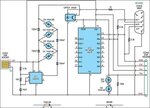
Of course you can, see example:

5-12V.jpg
 

Status
Not open for further replies.

Similar threads

Part and Inventory Search

Welcome to EDABoard.com

Sponsor

Back
Top