Continue to Site

Welcome to EDAboard.com

Welcome to our site! EDAboard.com is an international Electronics Discussion Forum focused on EDA software, circuits, schematics, books, theory, papers, asic, pld, 8051, DSP, Network, RF, Analog Design, PCB, Service Manuals... and a whole lot more! To participate you need to register. Registration is free. Click here to register now.

pic16f877a lcd 16x2 didn't work

Status
Not open for further replies.

ah xiang

Newbie level 4
Joined
Mar 7, 2015
Messages
6
Helped
0
Reputation
0
Reaction score
0
Trophy points
1
Activity points
46
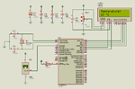
This is my program on MicroC PRO


Code C - [expand]
1
2
3
4
5
6
7
8
9
10
11
12
13
14
15
16
17
18
19
20
21
22
23
24
25
26
27
28
29
30
31
32
33
34
35
36
37
38
39
sbit LCD_RS at RB4_bit;
sbit LCD_EN at RB5_bit;
sbit LCD_D4 at RB0_bit;
sbit LCD_D5 at RB1_bit;
sbit LCD_D6 at RB2_bit;
sbit LCD_D7 at RB3_bit;
 
sbit LCD_RS_Direction at TRISB4_bit;
sbit LCD_EN_Direction at TRISB5_bit;
sbit LCD_D4_Direction at TRISB0_bit;
sbit LCD_D5_Direction at TRISB1_bit;
sbit LCD_D6_Direction at TRISB2_bit;
sbit LCD_D7_Direction at TRISB3_bit;
     int value ;
     char value1 [15] ;
 
void main() {
      TRISA.RA0=1;
      ADC_INIT();
      LCD_INIT();
      lcd_cmd(_lcd_cursor_off);
      lcd_cmd(_lcd_clear);
      lcd_out(1,1,"temperature");
      delay_ms(2000);
      lcd_cmd(_lcd_clear);
      lcd_out(1,1," temp ");
      while(1)
      {
      value=adc_read(0);
      value=value*0.488;
      floattostr(value,value1);
      lcd_chr(2,9,39);
      lcd_out(2,10,"C");
      lcd_out(2,1,value1);
      delay_ms(500);
      }
 
 
}


1388049_10205496607670801_327204991_n.jpgm.png

And this is the problem

Someone hlep me!!!
 
Last edited by a moderator:

Your circuit has any devices connected at MCLR and OSC pins.
 

andre_teprom:
protues.png
This is my old circuit...but also the same...have problem

betwixt:
Hi Brian,i didn't understand....can you gv an example for me? thanks
 

betwixt pointed that type of value is int and you are using it for floating point calculation.

If you are using 4 MHz crystal then set oscillator type as XT in Edit Project... If you have higher value crystal then set as HS.


Code C - [expand]
1
2
3
4
5
6
7
8
9
10
11
12
13
14
15
16
17
18
19
20
21
22
23
24
25
26
27
28
29
30
31
32
33
34
35
sbit LCD_RS at RB4_bit;
sbit LCD_EN at RB5_bit;
sbit LCD_D4 at RB0_bit;
sbit LCD_D5 at RB1_bit;
sbit LCD_D6 at RB2_bit;
sbit LCD_D7 at RB3_bit;
 
sbit LCD_RS_Direction at TRISB4_bit;
sbit LCD_EN_Direction at TRISB5_bit;
sbit LCD_D4_Direction at TRISB0_bit;
sbit LCD_D5_Direction at TRISB1_bit;
sbit LCD_D6_Direction at TRISB2_bit;
sbit LCD_D7_Direction at TRISB3_bit;
 
double value ;
char value1 [23] ;
 
void main() {
      TRISA.F0=1;
      LCD_INIT();
      lcd_cmd(_lcd_cursor_off);
      lcd_cmd(_lcd_clear);
      lcd_out(1,1,"temperature");
      delay_ms(2000);
      lcd_out(2,1," temp ");
      while(1)
      {
      value=adc_read(0);
      value=value*0.488;
      floattostr(value,value1);
      lcd_out(2,1,value1);
      lcd_chr(2,9,39);
      lcd_out(2,10,"C");
      delay_ms(500);
      }


And this is the problem

According to the picture above, you even connected the VDD / GND bus on the left side of the uC. Since simulation runs as expected, it seems that you are only facing a mounting problem of verifying prior to testing.
 

milan:
thanks for sharing...but also cannot to work...
i'm using 16x2 lcd 16pin...i think that's the problem...can hlep me to solve it?
 

Please zip and post complete mikroC project files. mikroC LCD code works only with HD44780 and compatible LCDs. It can work with 16x1, 16X2, 20x2, 20x4 LCDs.
 

Follow the advice you have been given.

From your photographs you have not even connected VSS and VDD and there is no crystal or it's loading capacitors and no supply decoupling. You also need to pull the MCLR pin to VDD before the processor will run.

It's difficult to see from the photograph but pin 1 of the LCD is in the corner of the LCD near the mounting hole. Check you have it connected that way.

If you correct the wiring and use the source code milan.rajik gave you it should work.

Brian.
 

betwixt please help me check it~
11014726_10205504385825250_949240400_n.jpg11047158_10205504374664971_1562071314_n.jpg
 

According to your picture first you have to check the two thing

1. MCU part
2.LCD part

1. You can simply connect one LED to one pin of MCU and modify the program writing to blink the LED which help you to confirm that the MCU part is working

then move to step 2

Hoped this will help
 

I still can't see clearly from the photographs. Use the two contact rows at each side of the board for VSS and VDD, it will make the layout easier and neater. For example, use the two outer rows for VDD and two inner rows for VSS, link them across from side to side to connect them together. Doing it that way keeps the VSS lines close to the PIC and also makes it easy to fit capacitors across VS and VDD.

Try to color code the wires if possible and make sure you connect both VSS pins to the negative rail and both VDD pins to the positive rail. You still seem to be missing the crystal loading capacitors and decoupling capacitors between VSS and VDD. They are necessary, it will not work without them.

Brian.
 

I can see the problem. I compiled the code you sent and the .hex file generated is different from the one that you had posted.
 

It don´t necessarily mean any problem, due to optimization settings that may different from his compilation.
 

betwixt: both of VSS and VDD is to their rail already...but the capacitor need put at where

milan:sorry for that...so which circuit better? And how to i do? :sad::sad::sad:
 

I just compiled his project. I didn't change anything.
 

Sorry for late reply - I'm trying to repair a spectrum analyzer with my other hand!

You need a capacitor from each end of the crystal to VSS, I suggest 20pF is a good value.

You should also add 100nF and 10uF in parallel across the VSS and VDD lines, as close as possible to the PIC. If you can add more 100nF capacitors across VSS and VDD at the LCD it may also help. They are important because the PIC and LCD need low impedance across their supply lines to work correctly.

Brian.
 

Check the attached .hex file in Proteus and also hardware. See attached image for circuit. I have compiled code for 8 MHz HS external oscillator.
 

Attachments

  • lab.rar
    86.6 KB · Views: 50
  • LM35 Thermometer.png
    LM35 Thermometer.png
    49.2 KB · Views: 61

Status
Not open for further replies.

Similar threads

Part and Inventory Search

Welcome to EDABoard.com

Sponsor

Back
Top