khan ali
Newbie

- Joined
- Feb 16, 2008
- Messages
- 5
- Helped
- 0
- Reputation
- 0
- Reaction score
- 0
- Trophy points
- 1,281
- Activity points
- 1,321
WoRkING detis FOR MICROCONTROLLER BASED DIGITAL STABLIZER KITS
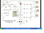
1 PHASE, 90 290 VAC 5 step
WIRING: Only one L.T. is required. Please do wiring as per above diagram.
SETTING: When you connect 95V input from variac the output should be 200V. Now increase
input and check output.When output reaches between 244/245V R3 goes ON and output will reach
near about to 205V. Run/check all steps.When you connect 290V input from variac the output should
be 240V.move preset 202(2k) till RL4 off.
LOW CUT SETTING: Low cut shall be work on connecting Jumper J2
INDICATIONS: If time delay mode is presented the LED blinks sholly at the time of power
on.If I\P voltage is out of range (high voltage) LED blinks fastly & /buzzer starts beeping also
fastly. If I\P low voltage range LED LED blinks slowly & buzzer starts beeping also slowly.
ANALOG CIRCUIT
1-0.18V transformer required.
2-Setting resets on faulty preset.
3-Capacitor value changes according to time & atmospheric changes and circuit start creating
problems.
4-Relay gives problems after some time
5-No High Cut Delay. Some times at the time of changing steps High cut starts
6-No Low Cut facility
7-Time delay circuit required & delay depends on Capacitor
8-No LED indication
9-No audio indication
10-Wiring is typical
11-Setting is based on 4 presets
DIGITAL CIRCUIT
1-No need of 0.18V transformer
2-Setting stored for life time
3-No possibility for this problem.
4-Relay works smoothly.
5-High Cut Delay is present and no possibility of fault High cut.
6-Low Cut facility
7-3mintus time delay and will remain same
8-LED indication on 2 LEDs for all modes
9-Audio indication for High cut & low cut
10-Single LT wiring is easy
11-Onlu high cut Setting on single preset
Hi,
Some body can help for mplab ide 8.60v error?
processor 16F676
#include <P16F676.INC>
__config 0x3F4C
; _CPD_OFF & _CP_ON & _BODEN_ON & _MCLRE_OFF & _PWRTE_ON & _WDT_ON
; & _INTRC_OSC_NOCLKOUT