Continue to Site

Welcome to EDAboard.com

Welcome to our site! EDAboard.com is an international Electronics Discussion Forum focused on EDA software, circuits, schematics, books, theory, papers, asic, pld, 8051, DSP, Network, RF, Analog Design, PCB, Service Manuals... and a whole lot more! To participate you need to register. Registration is free. Click here to register now.

Pic12F629 blowing up

Status
Not open for further replies.

Moonwalker

Member level 2
Joined
Jul 10, 2006
Messages
43
Helped
1
Reputation
2
Reaction score
1
Trophy points
1,288
Activity points
1,622
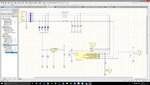
I have a circuit using a Pic12F629 as an rf transmitter on the Trailer socket on a truck (24V). I have 4 of these working perfectly but on one particular truck the Pic is failing after a few hours of use. First time both regulator and Pic failed and the second time only the pic failed. Now client called saying that it failed again. Last time I added a 5V zener before the 78L05 as extra protection in case of voltage going above 30V but something failed again it seems.
I have tested the truck voltage and it does not go above 28V with engine running.

Any idea what might be causing the Pic to fail?
 

Attachments

  • trtx.jpg
    trtx.jpg
    227.1 KB · Views: 128

Hi,

Automotive ... means a lot of noise ans spikes.
Your design needs to take care about this.

Protection circuits and good EMC proof PCB layout is urgent.

Klaus
 

I have several of these working on 12V systems without any problems and I have 4 others working on 24V systems. Its only on a particular truck that this is happening.

The 78L05 is indeed close to its input voltage limit but there are 2 diodes in series lowering the voltage to less than 27V. Also I have added a 5V zener in-series as extra protection but still got a failed pic. And the Input lines have 47k series resistors so even if they get higher than 5V the internal port protection should be able to handle it.

I will have a try with the MIC5281 and see if it holds.
 

A fully charged 24V battery will give 14.4x2=28.8V but it will be mostly close to 13.2x2=26.2V. During starting, battery voltage drops for a moment but picks up as soon as the engine starts. The battery acts as a huge capacitor and absorbs most of the voltage fluctuations but some will of course escape to other parts.

You can also try a two stage regulation: try a 15V regulator and run the 5V regulator from the 15V regulator output. That it is working on other trucks well simply suggest that there is nothing seriously wrong with the circuit itself.
 

I have several of these working on 12V systems without any problems and I have 4 others working on 24V systems. Its only on a particular truck that this is happening.

Besides this empirical results, there are requirements for transient withstanding and respective test specifications for electrical equipment used in road vehicles. Review e.g. ISO 7637-2 for details.

Look e.g. at test pulse 5a

test pulse 5a.png

If your device is designed to survive ISO 7637 test cases, it's unlikely to have any problems.
 

Ok I will try with the MIC5281 then. Looks like it can handle the above.

Do you think I should add protection to the Pic inputs?
 

Depends on what the inputs are connected to. If they are connected to other parts of the circuit that are VERY close to the PIC then you may not need to, but I'd say 'certainly' to anything else. As someone mentioned above, automotive electrics are very noisy with some very large spikes possible. I'd say that you should always assume the worst.
By the way, in your OP, did you really mean that you added a 5V zener BEFORE the 78L05; i.e. on the 24V side?
Susan
 

They are connected to 24V signals through a voltage divider of 47k and 10k resistors- so the pic sees 5V. Seeing the the current is quite low I did not include any protection since the Pic inputs have internal protection diodes already.

The 5V zener was connected in-series before the 7805 so that the voltage would drop to around 21V.
 

I have used 7805's on 24V road tankers BUT had a PTC, series input diode and TVS clamp for overvoltages.
75-100V spikes are common on big trucks. I'd recommend a HV regulator instead. A series zener is useless.

Check your design can handle an open ground. Trailer sockets frequently have corrosion and bad connections.
That can cause backfeed and blow I/O due to reverse-current.
 

A voltage divider using 47K and 10K will give less than 5V.

Zener diodes are not connected in series.

Voltage drop of around 21V will not work.
 

Check your design can handle an open ground. Trailer sockets frequently have corrosion and bad connections.
That can cause backfeed and blow I/O due to reverse-current.

If you see the circuit there is only 1 ground and if it disconnects no current can flow. I thought of this but cant see how a bad connection can cause any problem.

- - - Updated - - -

Zener diodes are not connected in series.

Voltage drop of around 21V will not work.

The zener was connected in series (reversed) so it drops 5V. Input is around 27V then 2 diodes in series making it about 26V and then the 5V zener making the input to the 7805 at 21V. I have tested this on the bench and was working as intended.
 

It is not good to feed the PIC from a voltage divider made of 47K and 10K. You just have a simple diode for protection. This is inviting disaster.

You should feed these inputs from the regulator output (OR) unless you have some other reasons. One diode in series is not enough protection.

The vehicle in question has some heavy duty accessories (Sound system or something like that)- that may generate too much noise?

Just curious- what the PIC is supposed to do?
 

I will suggest a few things to strengthen the circuit. I saw many vehicle designs fail, junior engineers in tears. Since you have no I/O to GND it's ok for open circuit there I believe.

Understand the voltage transients on a vehicle electrical system, using ISO 7637-2: "Road vehicles — Electrical disturbances from conduction and coupling — Part 2: Electrical transient conduction along supply lines only"

For a 24V system expect vehicle switching transients (test pulse 3a) -200V and inductive load switching (test pulse 1) -450V to -600V spikes. 12V system is -150V and -75V to -100V respectively.
1N4148's good for 100PIV, a bit low. I suggest ES1 600V 1A fast-recovery (SMA) part might fit on your PCB pads.

For positive spikes +100V (12V) and +200V (24V) at 0.2usec at 10kHz (test pulse 3b).
This is the one that kills the 7805 or even a MIC5281.

You must have a TVS and some series resistance on the input, to limit clamping current. Like 47R, this helps immensely.
Also 7805 can get hot on 28V, but I'm not sure total current including RF TX and LED.

FvM shows ISO 7637-2 (test pulse 5a) Load Dump but that is very difficult surge to tolerate, I don't bother designing for it unless I have lots of money.

If you are connecting to a trailer with ABS (SAE J560 connector), ABS braking high-voltage spikes can be present on the STOP lamp or AUX PWR line. I saw this on a trailer that kept blowing circuits up. Turning on gravel triggered the ABS.
 
Status
Not open for further replies.

Similar threads

Part and Inventory Search

Welcome to EDABoard.com

Sponsor

Back
Top