Continue to Site

Welcome to EDAboard.com

Welcome to our site! EDAboard.com is an international Electronics Discussion Forum focused on EDA software, circuits, schematics, books, theory, papers, asic, pld, 8051, DSP, Network, RF, Analog Design, PCB, Service Manuals... and a whole lot more! To participate you need to register. Registration is free. Click here to register now.

[SOLVED] [PIC] Why there is some error in SPI communication

Status
Not open for further replies.

milan.rajik

Banned
Advanced Member level 5
Joined
Apr 1, 2013
Messages
2,524
Helped
540
Reputation
1,078
Reaction score
524
Trophy points
1,393
Activity points
0
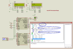
Why there is some error in SPI communication ? See image.

It only happens the first time communication is done. After that it works fine. I am testing it in both Proteus and hardware and I see same signals on both. In hardware I am using 2 x EasyPIC v7 development boards and Saleae Logic Analyzer.

What are those unknown datas ?

I am using CCS C as the Compiler. PICs used are PIC16F887.

broken link removed

I implemented SPI master slave comm in mikroC PRO PIC. See image. Even though LCD displays proper data the SPI debugger shows strange datas after first communication why ?

broken link removed


Edit: I am sorry, I was thinking that SPI data is sent continuously when in code I have written to transmit data when only data changes. So, the mikroC project is working fine. It shows different datas sent when datas change.
 

Attachments

  • SPI Master Slave.rar
    143.3 KB · Views: 133
  • spi master slave problem.png
    spi master slave problem.png
    64.7 KB · Views: 458
  • SPI Master Slave mikroC PRO PIC.rar
    163.4 KB · Views: 161
  • spi master slave mikroC PRO PIC.png
    spi master slave mikroC PRO PIC.png
    72.4 KB · Views: 263
Last edited by a moderator:

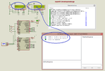
The CCS C project gives this result. See image. What does that message mean ? (circled message in image)

broken link removed
 

Attachments

  • spi m s.png
    spi m s.png
    73.8 KB · Views: 170
Last edited by a moderator:

The thread looks rather confused because you're incrementally editing it and posting completely different codes side by side without explaining anything about it. E.g. the first code you sent was changing the master/slave roles in operation, now you apparently cancelled this idea.

I'm not using Proteus and it's SPI debugger, but if you state:
Even though LCD displays proper data the SPI debugger shows strange datas
Did you consider a simple Proteus bug?
 
In the first post I posted two projects, one is CCS C and another is mikroC PRO PIC. The mikroC PRO PIC project works fine. The question regarding mikroC project is solved. I was watching changed datas on SPI debugger and was thinking that data is being sent repeatedly and got confused watching different datas in each communication.

The problem remains regarding CCS C project. What are those circled messages say ? Why I get those messages regarding one of the 4 bytes transmitted ? Even though it occurs the first time only the data on LCD is correct.

- - - Updated - - -

In the first post I posted two projects, one is CCS C and another is mikroC PRO PIC. The mikroC PRO PIC project works fine. The question regarding mikroC project is solved. I was watching changed datas on SPI debugger and was thinking that data is being sent repeatedly and got confused watching different datas in each communication.

The problem remains regarding CCS C project. What are those circled messages say ? Why I get those messages regarding one of the 4 bytes transmitted ? Even though it occurs the first time only the data on LCD is correct.

Did you consider a simple Proteus bug?

I am sure it is not a proteus bug because the code implemented in mikroC PRO PIC doesn't show those question marks in SPI debugger. It only happens with CCS C code.
 

You have huge delays between SPI bytes and SS operation. If it's not a Proteus bug, divergent SPI modes between master and SPI monitor are the most likely explanation. CCS SPI mode specification may be different from the industry standard.
 
I am sure it is not a Proteus problem. I added tris settings for PORTA and PORTB and the issue is partially solved. Now the unknow data (question marks) doesn't appear but in the 1st time SPI communication data is not going to slave. If I vary the pot and change the adc value then in the successive SPI communications data is reaching slave and being displayed on LCD. I am sure there is some problem in the CCS C generated code.

broken link removed
 

Attachments

  • SPI Master Slave rev1.rar
    294.2 KB · Views: 128
  • spi m s rev1.png
    spi m s rev1.png
    76.9 KB · Views: 187
Last edited by a moderator:

I don't see a SS activation event in the monitor display, which is at least strange.

All in all, it's just simulation, performed by a third-party tools so you can't be sure if it's modelling the Microchip processor correctly. If a real application fails, you can debug it at the source or assembly level and watch the waveforms with an oscilloscope.

I know why I don't use this kind of tools.
 
@FvM

I don't see a SS activation event in the monitor display, which is at least strange.

What do you mean by SS activation ? In SPI debugger it is showing Active / Inactive. Maybe it is SS activation. As I said earlier I am also testing in hardware with 2 x EasyPIC v7 development boards and Saleae Logic Analyzer. I see similar signals in Saleae Logic Analyzer except the dummy data shifted from the SSPBUF during 1st SPI communication is different. In hardware also SPI data (adc data from master) is reaching the slave but it is not being displayed on LCD during 1st SPI transmission but in successive SPI transmission it gets displayed. When 4 bytes is transferred then received flag has to set and display the data on LCD.

If SS activation is different from the one shown on debugger then explain it in more detail. By SS activation do you mean that in the first SPI transaction Active is not shown ?
 

Yes, you are right. Without a Active SS data will not be transferred. Don't know the reason for this. It only happens with CCS C. In mikroC I see perfect signals, even the first time.

Edit:

Problem solved. I read the CCS C manual and viewed the device header file and made changes to the code especially to the
Code:
setup_spi();
function and now the SPI signals are clean that is there are no question marks in the SPI debugger and also the data gets displayed on the LCD on first SPI transfer. There is one issue that is I still don't see an Active for the 1st SPI transaction.

broken link removed
 

Attachments

  • spi m s rev2.png
    spi m s rev2.png
    60.5 KB · Views: 163
  • SPI Master Slave rev2.rar
    266.7 KB · Views: 97
Last edited by a moderator:

You simply forgot to setup the SS pin high before starting the communication. It's necessary to reset the slave logic.

In the mikroC project, you have
Code:
Chip_Select = 1;
 

Maybe you are confused. I am talking about CCS C project. This is the code of CCS C Project.


Code C - [expand]
1
2
3
4
5
6
7
8
9
10
11
12
13
14
15
16
17
18
19
20
output_low(SS_PIN);    //pull the slave select line low to select the slave
         delay_ms(100);          //give the slave time to notice this (may be unnecessary)
                  
         spi_write(fvalue.bytes[0]);  //send the value
         spi_read();
         delay_ms(100);        
         spi_write(fvalue.bytes[1]);
         spi_read();
         delay_ms(100);                        
         spi_write(fvalue.bytes[2]);
         spi_read();
         delay_ms(100);
         spi_write(fvalue.bytes[3]);
         spi_read();
                     
       
         delay_ms(100);          //(may be unnecessary)
         output_high(SS_PIN);   //deselect the slave. 
       
         delay_ms(100);


In the mikroC code I have.


Code C - [expand]
1
2
3
4
5
6
7
8
9
10
Chip_Select = 0;
              SPI1_Write(fValue.bytes[0]);
              Delay_ms(200);
              SPI1_Write(fValue.bytes[1]);
              Delay_ms(200);
              SPI1_Write(fValue.bytes[2]);
              Delay_ms(200);
              SPI1_Write(fValue.bytes[3]);
              Delay_ms(200);
              Chip_Select = 1;


Edit: Ok. I understood what you were trying to tell. You were saying that after SPI is setup the SS pin has to be made high. Ok. You are absolutely right. I made the changes and now the debugger shows Active for the first SPI transaction.


broken link removed
 

Attachments

  • SPI Master Slave rev3.rar
    311.5 KB · Views: 120
  • spi m s rev3.png
    spi m s rev3.png
    43.2 KB · Views: 185
Last edited by a moderator:

Status
Not open for further replies.

Similar threads

Part and Inventory Search

Welcome to EDABoard.com

Sponsor

Back
Top