pjohn
Newbie level 6
Dear All,
I have been working on a prototype of Buck converter, I have been using PIC18F25k80 in order to generate Complementary PWM using ECCP, I am only using one of the PWM pin at the moment for switching Logic MOSFET, as in the future I would like to make the Synchronous buck conveter hence Complementary PWM.
Here are my System Parameters and components:
Vin = 12v
Vout = 5v
Duty Cycle = 41.5
Iout = 2A
Switching Frequency = 7.5 Khz
Inductor = 1000uH
Diode = Schottky 3A
Cin = 47uF
Cout = 1000uF
I get the Complementary PWM on both the pins (Confirmed using Oscilloscope), I also Get the required output Voltage i.e. 5v, but as soon as I put any load on it (LED, 10mA) my Voltage gets reduced to 1v for some reason.
I have tried changing the Duty Cycle when drawing 10mA but it does not effect the output, when Duty Cycle is 90%, the maximum I get is 3v at 10mA load. Please help me, as I am lost what I am doind wrong.
The way I calculate my PWM is, I Measure the output Voltage, using ADC, and incease or decrease the duty cycle untill Output Voltage is 5v, is this how PWM Duty cycle is adjusted using Feedback?
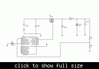
I have also attached my circuit, Any Help or direction will be highly appreciated.
Best Regards
I have been working on a prototype of Buck converter, I have been using PIC18F25k80 in order to generate Complementary PWM using ECCP, I am only using one of the PWM pin at the moment for switching Logic MOSFET, as in the future I would like to make the Synchronous buck conveter hence Complementary PWM.
Here are my System Parameters and components:
Vin = 12v
Vout = 5v
Duty Cycle = 41.5
Iout = 2A
Switching Frequency = 7.5 Khz
Inductor = 1000uH
Diode = Schottky 3A
Cin = 47uF
Cout = 1000uF
I get the Complementary PWM on both the pins (Confirmed using Oscilloscope), I also Get the required output Voltage i.e. 5v, but as soon as I put any load on it (LED, 10mA) my Voltage gets reduced to 1v for some reason.
I have tried changing the Duty Cycle when drawing 10mA but it does not effect the output, when Duty Cycle is 90%, the maximum I get is 3v at 10mA load. Please help me, as I am lost what I am doind wrong.
The way I calculate my PWM is, I Measure the output Voltage, using ADC, and incease or decrease the duty cycle untill Output Voltage is 5v, is this how PWM Duty cycle is adjusted using Feedback?
I have also attached my circuit, Any Help or direction will be highly appreciated.

Best Regards