Continue to Site

Welcome to EDAboard.com

Welcome to our site! EDAboard.com is an international Electronics Discussion Forum focused on EDA software, circuits, schematics, books, theory, papers, asic, pld, 8051, DSP, Network, RF, Analog Design, PCB, Service Manuals... and a whole lot more! To participate you need to register. Registration is free. Click here to register now.

[SOLVED] Pic 16f876a Pure Sinewave inverter

Status
Not open for further replies.
hey man do u know if i wanna omit all feed backs except vout what should i cancell in the software i mean i want it always to go to normal more and i know i can do it by hardware but i wanna see if u know how to do it by software cz i wanna do another pic that controls all these stuff and don't know anything about ccs c compiler i work with picbasic
 
Last edited:

hi guys ...can any one please help me in this code ... i want to generate sine pwm of 50 hz and using a crystal of 12 MHZ....please help


#include <18f452.h>
#device HIGH_INTS=true
#fuses HS, NOWDT, PUT, NOLVP
#use delay(clock=12000000)

const long sine[32] = {0,5,9,14,18,23,27,31,34,37,40,42,44,46,47,48,48,
48,47,46,44,42,40,37,34,31,27,23,18,14,9,5};

int i=0;


#INT_TIMER0 //HIGH
void timer0_isr()
{
clear_interrupt(INT_TIMER0);
set_timer0(254);
set_pwm1_duty(sine);
i++;
if(i=32)
i=0;
delay_us(5);
}

void main()
{

setup_timer_2(T2_DIV_BY_1, 250, 1); //51.2us
setup_ccp1 (CCP_PWM);
set_pwm1_duty(200);
set_timer2(0);

setup_timer_0(RTCC_INTERNAL|RTCC_DIV_8|RTCC_8_BIT);
set_timer0(254);
enable_interrupts(INT_TIMER0);
enable_interrupts(GLOBAL);
delay_ms(5);
while(true)
{
;;
}
}
 

hey californiajoe check this out that's the modification i did its in phase with the output signal im getting a pure sinewave with no interference but still i have no voltage regulation the output of the op-amp is 2.51vi tried interchanging vac1 with vac 2 nothing changed. if i used a 50w bulb if my voltage is 220 it will become 207


NB: could my transformer be the problem i took it from an old pur sinewave Chinese inverter its 230 : 6 v but if so y am i being able to change the voltage when i trime the pot in my schematic??
 

Attachments

  • amp.pdf
    9.5 KB · Views: 423
Last edited:

man if it was the zener doing the problem so how come if i varry the pot the voltage changer?
anyways i wil try to take them off. can u tell me on ur side what is the ac voltage after the two 10 M resistors?
 

I am not sure about zener, ac voltage behind 10M resistor is somewhere in range of 2,5V, but it is not straight, it has the same shape as 230VAC (in mV ofcouse). Phase of it ont the output of OP amp is important for correct work of the inverter.
 

well i reput the two 10M resistors and the invertor is working fine i have regulation and 230v butttttttttt i have the flickering again :mad: do u have any idea how to make the feedback withough the 10M resistors??? plz help me im out of ideas
 

any idea whats the problem of using a transformer between them ???
 

anybisi said:
Hi
how do i attach the schematics and the program i got from the net
thanks
Here you have a possibility to attach anything you want.


---------- Post added at 14:13 ---------- Previous post was at 14:11 ----------

For zouzanda:
As I told you, I've done it by Taner's idea and it works well, I don't know if idea with transformer is doable. It should be tested and only you can test it. Obviosly your desighn of PCB is not desighned well, otherwise you would not have problems with flickering. You have to know that there is very big possibility that you have more than one problem on your PCB plate.
 

ok im back again i just need to ask one last Q what should be the output voltage when we apply a load will it stay 230 or it decreases???
 

upto 80 percent of load output ramains 230v, butt after that it will gradually (in some cases sharp) decrease as load is increased
 

OK AFTER CALIFORNIAJOE TOLd me that my pcb might be wrong i doubted myself and i did tyner design and still i have same results i have a perfect regulated invertor nomatter what load i put i will have a 230v on the output but the thing is that if i have a small load like 50 w light bulb i will see flickering and if i connect an oscilloscope on the output the flickering increases please i need someones help if jami has any idea please give it to me. one more thing the wave is like in the image
 
Ok, I will try to help you (also, I would invite jami007 to join our discusion), but you have to strictly follow instruction. We will do it step by step.
Two hex files are attached here, try to load them into MCU (one by one) and try to do the same test every time (I suppose that you have connected all important signals to MCU). Use osciloscop and check shape of the signal on MCU pin 12 and pin 13. It would be very usefull, if you could make a picture for each signal and if you could meassure a frequency of each signal.
As you can see, my idea is following these two signals from MCU to output. So I am waiting.
 

Attachments

  • sine-wave_inverter_without_a-b_voltage_check.rar
    9.8 KB · Views: 408

well now im not home ill reach home in couple of hours the mosfet im using are ir3205 they are compatible i'm sure they have low rdson btw im an electrical engineer and i've been working in invertors since 7 year i actually have my own sinewave invertor but im intrested in this project and i wanna do it even though i know there should be lots of upgrades in the power board but that will be done after i'm done making this invertor work and the problem is i dont like to start something i can't finish soo again thank all of u guys for the effort
 

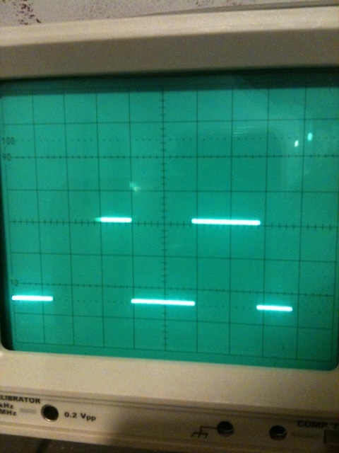
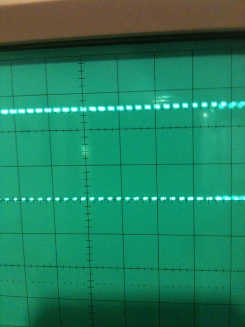
here are the results that i got from the hex u gave me without a/b check btw the other file didnt even start A/B = 50hz pwm around 20Mhz uu can see in the images

2_1325527734.jpg
36_1325527734.jpg
 

you got true results, A/B is a 50Hz, 50% duty cycle signal
 

ok now i found the mistak see the attatched image its A/B vs vout
 

Status
Not open for further replies.

Part and Inventory Search

Welcome to EDABoard.com

Sponsor

Back
Top