Continue to Site

Welcome to EDAboard.com

Welcome to our site! EDAboard.com is an international Electronics Discussion Forum focused on EDA software, circuits, schematics, books, theory, papers, asic, pld, 8051, DSP, Network, RF, Analog Design, PCB, Service Manuals... and a whole lot more! To participate you need to register. Registration is free. Click here to register now.

Physical Winding Configuration

Status
Not open for further replies.

sabu31

Advanced Member level 1
Joined
Jan 28, 2011
Messages
446
Helped
12
Reputation
24
Reaction score
13
Trophy points
1,298
Activity points
5,157
Dear All,

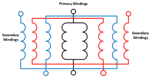
I need to design a pulse transformer with input 500V, output 4kV. Pulse width 10us and rise time 1us. Load on secondary 60 Ohms. I have made pulse transformer however, there are still issues of ringing. I came across a paper which mentions a particular configuration of secondary winding which gives tight coupling. I understand that primary is wound on two legs of C core and are connected in parallel. But not able to understand secondary winding configuration. I am attaching the figure. Could someone translate it to a physical connection on a C core.

Thanks in Advance
 

Attachments

  • Drawing1.png
    Drawing1.png
    19.3 KB · Views: 102

each leg of the C core has a primary winding and three secondary windings.

the two primary windings are connected in parallel, so that the induced magnetic field in the core add (in parallel) not anit-parallel

on each leg of the C core, the inner and outer secondary winding and the center winding of the other leg are connected in parallel,
so that the induced currents are all in the same direction

consider the blue secondary - current "enters" at the upper right and goes "down"
it then goes to the center secondary on the other leg, where the current goes "up"
it then goes to the inner winding on the original leg, where the current again goes "down"

To actually wind this, each leg has a bobbin with 4 windings, 1 primary and 3 secondaries.
Then connect the starts and finishes of each winding together correctly so the current path
of the primaries are consistent with adding magnetic flux in the core, and so that each secondary,
red and blue in your picture, are wired correctly so that the induced currents add.
than connect the two secondaries in series.

don't forget appropriate insulation between layers, etc.
 

    sabu31

    Points: 2
    Helpful Answer Positive Rating
Thankyou wwfeldman for the reply.

I have two queries related to this.

a. Should the primary be inner layer (assuming its low voltage winding) or should it be in between the secondaries
b. Generally, we say increasing the number of layers increases leakage but reduces capacitance.. How is it that in this case the leakage is reduced.
 

go back to the paper that provided the picture of the winding configuration
it should, at least (?), answer a and provide some insight into b.
 
Status
Not open for further replies.

Similar threads

Part and Inventory Search

Welcome to EDABoard.com

Sponsor

Back
Top