mshh
Full Member level 6

- Joined
- May 30, 2010
- Messages
- 349
- Helped
- 0
- Reputation
- 0
- Reaction score
- 0
- Trophy points
- 1,296
- Location
- usa
- Activity points
- 3,871
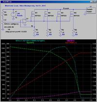
I am doing maximum power tracking (MPPT)for a photovoltaic cell (max current 4.8 A ,max voltage 34 v) i did this circuit [url=https://obrazki.elektroda.pl/8348410600_1385718504.jpg] [/URL]to control current consequently get MPPT but the circuit go mad when i turned the potentiometer the current go up and down and didn't stabilize .
I used this power supplyhttp://www.amazon.com/Mastech-HY3005.../dp/B000E14F56 to simulate the pv panel and adjust it to source 7 volt and it did well . i could change the current from 0-2 A when i tried to increase it upper than 7 v it went crazy . the led indicator called C.C changed to C.V every thing current and voltage go upside down ,and that what was happening with the pv panel. i don't know why . may be i should increase the number of mosfets.
- - - Updated - - -
 [/URL]to control current consequently get MPPT but the circuit go mad when i turned the potentiometer the current go up and down and didn't stabilize .
I used this power supplyhttp://www.amazon.com/Mastech-HY3005.../dp/B000E14F56 to simulate the pv panel and adjust it to source 7 volt and it did well . i could change the current from 0-2 A when i tried to increase it upper than 7 v it went crazy . the led indicator called C.C changed to C.V every thing current and voltage go upside down ,and that what was happening with the pv panel. i don't know why . may be i should increase the number of mosfets.
- - - Updated - - -
but i used four resistors 3.3Ω 7 watt instead of those in pictureI am doing maximum power tracking (MPPT)for a photovoltaic cell (max current 4.4 A ,max voltage 34 v) i did this circuit [url=https://obrazki.elektroda.pl/8348410600_1385718504.jpg][/URL]to control current consequently get MPPT but the circuit go mad when i turned the potentiometer the current go up and down and didn't stabilize .
I used this power supplyhttp://www.amazon.com/Mastech-HY3005.../dp/B000E14F56 to simulate the pv panel and adjust it to source 7 volt and it did well . i could change the current from 0-2 A when i tried to increase it upper than 7 v it went crazy . the led indicator called C.C changed to C.V every thing current and voltage go upside down ,and that what was happening with the pv panel. i don't know why . may be i should increase the number of mosfets.
