Continue to Site

Welcome to EDAboard.com

Welcome to our site! EDAboard.com is an international Electronics Discussion Forum focused on EDA software, circuits, schematics, books, theory, papers, asic, pld, 8051, DSP, Network, RF, Analog Design, PCB, Service Manuals... and a whole lot more! To participate you need to register. Registration is free. Click here to register now.

[SOLVED] Photodiode Fast detection !!!!

Status
Not open for further replies.

chippevijaya

Member level 1
Member level 1
Joined
Apr 26, 2013
Messages
33
Helped
3
Reputation
6
Reaction score
3
Trophy points
1,288
Visit site
Activity points
1,549
Dear friends,
I am new to photodiodes and their usage, please some one will solve my problem,

I am using the PIN photodiode and avalanche photodiode in photovoltaic(zero bias) modes. But i am unable to get the pulse of 50ns (sending from the laser).
I am sending the 50ns pulse from laser and the APD is placed at the 10cm distance. But the output of the APD is in 10us to 60us varying pulse to pulse.
I have observed one thing that the rise time of the APD response is very sharp(<5ns) but the falling is taking very slow till 10us.
Both APD and PIN diodes are having 1ns rise and fall times, so it has to rise and fall with 50ns pulse with exact timing, but why it is not happening.
 

How are you using an APD with zero bias? Normally they would be reverse biased with 100-300V otherwise there is no point. If you want speed then you need to reverse bias your PIN as well. The other requirement for speed is a low impedance load - either resistor or transimpedance amplifier. For checking lasers a simple PIN with 47 ohm resistor and PP3 battery to reverse bias it with 9V works well.

Keith
 

Avalanche operation with zero bias is like mountaineering on the sea. Good luck! :smile:

Besides specified bias, a suitable load, e.g. 50 ohm resistor (passive) or TIA (active), is required.
 

Dear friends,
i had tried with reverse bias of 30V applied to the APD, it doesn't improved the performance. In datasheet it showing that breakdown voltage is 160-240V. so i have to apply 160V....to APD to work it properly?

APD datasheet link : **broken link removed**
 

Normally you run an APD within a few volts of breakdown. With yours I would have thought around 200V for a magnification of 100 would be a typical working point. In total darkness you could run even higher. There is a lot of variation from one device to another and they are very temperature sensitive so you cannot use a fixed voltage. However, I think the impedance of your sensing circuit (resistor? transimpedance amplifier?) could be a problem as well.

Keith
 

OK friends I understand the concept of avalanche photodiodes, i had applied 60V to bias the APD, its performance has got changed and getting little sharp response from the photodiode.
But does any one tell me the circuit for generating 200Vdc from 5Vdc. I have looked LT3482, MAX1932, but they are giving upto 85Vdc Max. does anyone have 200Vdc generation since, my APD is having M=100 at 200Vdc supply.
 

Post your schematic.
Until you have a decent photodiode load/amplifier there is no point building an APD power supply. You should be able to get the speed you need with a PIN diode first, then when the amplifier is sorted you can move to the APD.

You need a power supply chip with an external transistor such as LM3488. While TI/National say it is 40V maximum output voltage that is rubbish - there is no logical reason to limit it to 40V - I have used them for several hundred volts.

Also, from the forum rules:

Do not contact users asking for help or to advertise
Don't make requests for help in private using personal messages, create a thread in the forum so that other members can benefit from the posted answers.

Keith
 
First, you need to collect the photocurrent by drift and not
by diffusion. This means the depletion region must be maximized
relative to device volume. High reverse bias is desirable. Your
choice to run in another mode is counter to the interest in
speed. A diode meant for this mode might do better than
one designed to achieve larger depletion volume (sensitivity)
run at an inappropriate bias.

Two, your input impedance must be low if you want
bandwidth to be high. The diode's self-impedance will
be high at low photocurrents and near-zero Vf; any
resistive load will steal signal. Using a well biased
photodiode to throw current at a low impedance, with the
impedance leading to a variable voltage source that is
kept just under threshold, would be a good approach.

I doubt that sensitivity is a key attribute here so you
may even want to rethink the whole choice of detector -
would a fast phototransistor in emitter follower mode,
or even a Schottky chip, work as well? You can measure
the delivered photocurrent and see what kind of signal
you get.
 

Thank you Keith,
I had implemented the amplifier using --PIN diode of PS1.0-5(ps: attached datasheet) --> RC low pass filter --> OPA380 TIA --> TLV3501 comparator -->microcontroller and it worked well, but now 1) i am sending the information for long range(>300 mtrs) to receive and
2) <100ns pulses are using, so now i am trying with APD. I had tried with MCP664(four op-amps in single IC) connected as above, it also given good results.

I hope the same circuit works with APD, or i have to choose different amplifier?
 

Attachments

  • PS1.0-5 TO 500127 500128.pdf
    647.3 KB · Views: 123

Listing a few ICs isn't a schematic and doesn't tell everything about how you are trying to interface to the photodiode (e.g. RC low pass filter before the TIA? what feedback resistance and capacitance do you have on the OPA380?). It is not clear from your initial post if the PIN diode solution worked satisfactorily or not.

However, in general, the signal processing from a PIN diode and APD are pretty much the same. The only extra consideration with the APD (in addition to the requirement for temperature compensation of the APD bias votage) is to make sure that APD overload won't blow up either the APD or TIA.

If you are transmitting by line of sight (point to point) then 300m should be no problem with well designed optics with a PIN photodiode. With 25mm optics, 50mm focal length, at 300m a 4W laser should give you more than 10mW at the receiver assuming 60um laser. That is huge. It is different if you are designing a rangefinder where the laser hits an object and is scattered where the returned signal will be more like 1nW.

Keith
 

dear keith,
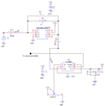
Please find the attached datasheet of my schematic, and there are small changes made in circuit externally not yet updated in Schematic, one is Pin diode anode is given to "-20Vdc" for photoconductive operation by tapping wire and another is AC coupling RC circuit (sorry i said RC lowpass filter in earlier post but in final i connected AC coupling to reduce the daylight level shift...) and capacitor value is changed to 47pf for instance under sunlight, and resistor to 1Mohms. And feedback resistor at OPA380 changed to 100K to increase the gain...
And for your explanation, you are right, that i am sending with line of sight, it reached up to 85 mtrs with our testing(CW Laser diode of 500mW, driven at 10nJ of pulse power).

But now i am implementing with PLD of 25W driving at 60nJ power and APD @ receiver.
 

Attachments

  • untitled.png
    untitled.png
    25.7 KB · Views: 131

PD bias circuit is missing in the schematic. The comparator doesn't work due to floating input.
 

Yes in schematic it is missing but i connected Pin diode anode is given to "-20Vdc" for photo-conductive operation by tapping wire, explained in the theory, The PD is biased.
 

If you connect the anode to -20V instead of GND there is still no DC path for the photodiode. Normally the photodiode would be DC coupled directly to the TIA input. You still have no DC bias based on your description.

Keith
 
Status
Not open for further replies.

Similar threads

Part and Inventory Search

Welcome to EDABoard.com

Sponsor

Back
Top