Continue to Site

Welcome to EDAboard.com

Welcome to our site! EDAboard.com is an international Electronics Discussion Forum focused on EDA software, circuits, schematics, books, theory, papers, asic, pld, 8051, DSP, Network, RF, Analog Design, PCB, Service Manuals... and a whole lot more! To participate you need to register. Registration is free. Click here to register now.

photodetector or Ambient light sensor

Status
Not open for further replies.

aamit4

Newbie level 5
Joined
Apr 11, 2012
Messages
9
Helped
0
Reputation
0
Reaction score
0
Trophy points
1,281
Activity points
1,372
Hello,

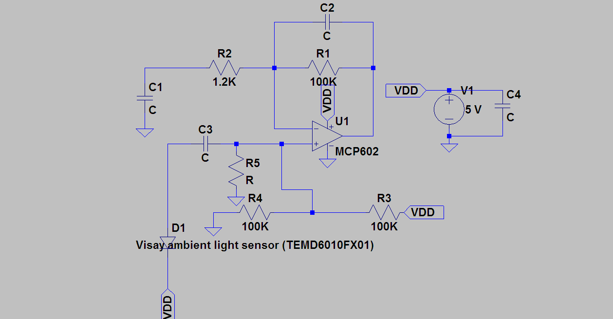
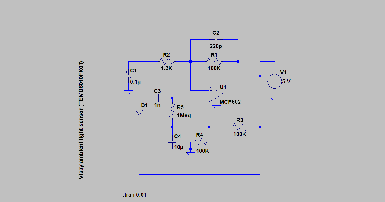
I am trying to build phototdetector circuit that would detect blinking LED, that's the data. I am using ambient light sensor from Visay (TEMD6010FX01)and MCP602 single supply op-amp. My circuit would work without biasing non-inverting(+) pin such as at mid-supply (2.5V). But, when i biased it with 2.5V using voltage divider, op amp would saturate, i would see straight line at 5V on oscilloscope. Also, how do i determine the correct value for coupling capacitor (C3) and bypass capacitor (C1), feedback C2. Also, do i need to put connect resistor from + pin to ground. i have attached an image on my circuit Can anyone help me please? Thank you in advance.


R5 throws a tilt into your R3 and R4 network since it is in parallel with R4.

Your sensor signal may not be getting amplified properly. Try connecting it to the inverting input rather than the non-inverting. The signal should go through R2.

By including a capacitor inline it may or may not adversely affect performance.

Does the sensor change in resistance? Does it produce a DC voltage? These factors will determine what bias level needs to be applied to the non-inverting input.

Your gain appears to be set up as 83 (and some hi-freq reduction). If the output stay at 0, or 5V, then try reducing gain until the trace moves into a middle region. Then you can shine light on the detector and see how it responds.

You'll have to experiment with the capacitor values. It's hard to predict which values will give you the desired performance. Impedance in the components makes a difference what time constant is at work.
 
Last edited:

I think there is something wrong with what you have built - it cannot match your circuit. If you bias the non-inverting input at 2.5V then the inverting input and output will also be at 2.5V in the absence of a modulated light source. If you are getting 5V then you built it incorrectly.

Keith.
 

BradtheRad and keith1200rs,tThank you for your help. I have changed my circuits little bit. see the image. Now, i'm seeing my amplified signal and bias point is 2.5v. But i still want to amplified further. Do i need to add coupling capacitor for the next stage? would it be fine if i connect straight to next stage? As far as choosing a right capacitor value, i know the formula for cut of frequency Fc=1/(2*pi*C*R). Using this formula i can solve for C right? if i know the FC and R. but, i can't seem to find right value. Is there a rule of thumb to to start value for C? My sensor ouputs small ac signal around 40mv 50mv.Thanks


There are several branches of resistance inline with C3. It charges and discharges through these branches.

To use the formula you will need to determine how much overall resistance they create. This includes the photosensor's resistance values when it is dark, and when it is illuminated.

The goal is to choose a capacitor which is not too large or too small.

This post is not to say whether you do or do not need a capacitor in line with the photosensor.
 

Isn't the current of the light sensor (D1) always in one direction if biased by a reverse voltage? What is the role of C3? What is the reverse voltage on the sensor?
 

Status
Not open for further replies.

Similar threads

Part and Inventory Search

Welcome to EDABoard.com

Sponsor

Back
Top