Continue to Site

Welcome to EDAboard.com

Welcome to our site! EDAboard.com is an international Electronics Discussion Forum focused on EDA software, circuits, schematics, books, theory, papers, asic, pld, 8051, DSP, Network, RF, Analog Design, PCB, Service Manuals... and a whole lot more! To participate you need to register. Registration is free. Click here to register now.

Photo diode and IR led

Status
Not open for further replies.

zawminoo

Advanced Member level 4
Joined
Dec 6, 2005
Messages
105
Helped
4
Reputation
8
Reaction score
1
Trophy points
1,298
Activity points
2,233
Hi everybody...
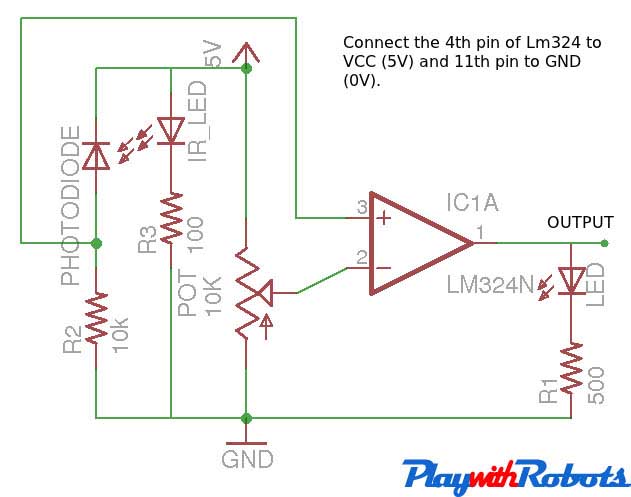
I would like to make line follower sensor with photo diodes.
As following figure..
**broken link removed**

They use two diodes.
But I have only a photo diode and 3 pins IR led.

2177197_f248.jpg
1276332227582_hz-myalibaba-web5_4376.JPG


How can I do? Please help me.
 

A line follower requires two diodes. With only one photodiode you can try to follow the straight line from one side but once the line twists, your device will be lost. Get two photodiodes!
 

The one you named "3-pin IR LED" is actually an IR receiver.

The IR receiver detects an IR beam if it is pulsed at a frequency about 38 KHz (the exact frequency may differ from one type to another).
In this case, you just need, perhaps by using 555 timer IC, drive your IR LED with pulses around this frequency. You may like changing it a bit to get best sensitivity at the IR receiver.
Usually (the ones I have), the output of the IR receiver becomes low when the pulsed IR beam is detected.

The IR receiver pins are for:

Vcc (positive, say 5V)
GND
Data (it may need an external pull-up resistor, say 4K7)

Since you don't have its datasheet, you likely need discovering the function of the 3 pins by a test (while the IR LED is pulsed).
I suggest you connect, during your tests, a resistor in series with 5V. Its value could be 1K (to limit the current in case of reverse connection). If in all tests the drop on 1K is relatively big and you couldn't discover the data pin, you may decrease it to 470R, but not less than 220R (the IR receiver should certainly work with the latter one if its pins are connected properly). Of course, later you can remove this current limiting resistor when pins are identified.

Note:
Using the IR receiver is a better solution than using an IR photo-diode. The beam detection sensitivity will be independent of the ambient light, practically speaking.
 
Last edited:
Sorry for above photos. The black diode is IR transmitter diode and can see in TV remote control. 3 pins diode is IR receiver.
Most of line follower robot used a IR transmitter diode and a photo diode (for IR receiver).
I would like to use 3 pin IR receiver instead of photo diode.
Can I replace IR receiver directly.

In this figure, I want remove photo diode and place 3 pin IR receiver.
May be OK? What I modify or change the circuit?
 

An IR receiver ignors continuous IR (like interference from sunlight) because the IR must be modulated on and off at about 38kHz. The 38khz cannot be continuous (like interference from a compact fluorescent light bulb) but must have "bursts" of 38kHz or it will also be ignored.
 
May be OK? What I modify or change the circuit?

As Audioguru pointed it out, your circuit needs to be split to:

Transmitter: by using the 555 timer IC for example, to generate the 38 KHz (actually it is the carrier frequency for which the IR receiver is designed) for the IR LED.

Receiver: It usually gives a low output when IR bursts are detected, otherwise the output is high.

Please note, there is nothing for free because the response of the IR receiver is much slower than of the photo diode.
The typical time of its reliable response is about 500 us (based on the IR receivers I work with).

Kerim
 
Status
Not open for further replies.

Part and Inventory Search

Welcome to EDABoard.com

Sponsor

Back
Top