Continue to Site

Welcome to EDAboard.com

Welcome to our site! EDAboard.com is an international Electronics Discussion Forum focused on EDA software, circuits, schematics, books, theory, papers, asic, pld, 8051, DSP, Network, RF, Analog Design, PCB, Service Manuals... and a whole lot more! To participate you need to register. Registration is free. Click here to register now.

Phase response of Opamp in Monte Carlo Simulation

Status
Not open for further replies.

thikgaidep

Newbie level 6
Joined
Aug 22, 2012
Messages
12
Helped
0
Reputation
0
Reaction score
0
Trophy points
1,281
Activity points
1,409
hello everyone,

I finished a schematic of single-output folded cascode opamp and did the simulation with it in Cadence. The config of the testbench is that the output of the opamp is connected to its negative input in order to fix the DC point. When I do the Monte Carlo Simulation with 100 samples, there are about 27 abnomal phase responses of the Opamp as follow:
View attachment 123.bmp

it means that in the 27 samples, at low frequencies, the phase is -180 instead of 0 as those of the remain 73 phase responses.
I would like to ask you if my opamp is unstable with those 27 samples or not? And where is the abnomal from, how can I deal with it?

I would be very appreciated. Thank you in advance,

Best regards,
thikgaidep
 

From the magnitude response curves I deduce that the gain continuously is decreased - that means: Rising feedback factors.
Your phase response curves show that for some feedback factors (above a certain limit) the amplifier is unstable.
This is because a rising phase shift for rising frequencies indicates instability.
Remember: Rising feedback reduces the stability margin.
 
Last edited:
Thank you LvW, but in my monte carlo transient simulation, I can not see any unstability with my Amplifier circuit based on the Opamp mentioned above. The 200 samples of transient simulation are following:
View attachment 1234.bmp

If transient says nothing about the stability, could you please suggest me methods to detect the unstability of a circuit. Thank you in advance,

Best regards,
thikgaidep
 

thikgaidep,

at first, I don't understand the signals in your "transient simulation". To test a linear amplifier I would expect sinusoidal signals (input and output).

Secondly, regarding the ac simulation it is important to see the relation between magnitude and phase. Therefore, repeat the simulation with much less parameter steps (only 5...10 curves).
And it is important to describe the feedback - if any.
 
Thank you LvW,
I used the sc amplifying to test with dc input signal. Thus, the output is in dc form, too. The prob is that I can not see any oscillated signal in my amplifyer circuit although the opamp ac test shows unstability in 30% of Monte Carlo sim samples. The prob stands for itself for cases of less or higher number of Monte Carlo runs.
Do you think that there is a prob with my ac simulation configuration (I connect the single output to the negative input (negative feedback), and the other possitve input is connected to a reference level, by which the dc level of the output is fixed to the ref value. And I simulated the ac response of the buffer and derived the ac response of the opamp)?

Thank you in advance and best regards,
thikgaidep

I must confess that I didn't understand all of your formulations - in particular those in red.

I suggest to show us a circuit diagram (including, of course, any feedback alternatives.)
 
Dear LvW,
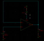
Following pic is the ac-dc setup simulation of my opamp. And the output monte carlo is in the pic 123.bmp above.
AC_Sim.png
Then, following is the amplifier setup simulation with an DC input. Initially, the opamp is reset by the AMP_RST signal and then it amplify the dc input. The monte carlo ouput wave form is in the pic 1234.bmp above.
Amp.png

Thank you and best regards,
thikgaidep
 

Here are my questions:

1.) How is the opamp powered (single or double supply)?
2.) What is the role of Vref in the first picture?
3.) What is the purpose of Vref in the 2nd picture?
4.) Did you realize that the inv. input in the 2nd picture is floating? No dc path available!
5.) Did you check the dc operating point of the amplifier?


1) It is single powered opamp
2) There are 2 inputs and only 1 output of the opamp. Therefore, the positive input is assigned with a Vref voltage to bias the DC level, by which the DC level of the output is fixed to Vref.
3) There are a reset phase in pic 2 to connect the output and the negative input in order to fix the DC level of the output. When the reset phase is over, the DC of the output is Vref (similar to pic 1), and the input is applied. Thus, the amplifier can work in desired DC config.
4) The DC level of the negative input is fixed in the reset phase.
5) Yes, I did. and the dc level is ok.

There are mis-matchings in monte carlo simulation of ac response in pic 1 with the transient response in the pic 2. The 1st sim shows that the opamp is unstable in 30% of monte carlo runs, but there is no oscillated in the transient monte carlo simulation. Would you plz give me some explains and tell me an appropriate method to test the stability of my circuit. I would be much appreciated.

Best regards,
thikgaidep
 

Hi thikgaidep,
please find some remarks below (in green)

1) It is single powered opamp
which value?

2) There are 2 inputs and only 1 output of the opamp. Therefore, the positive input is assigned with a Vref voltage to bias the DC level, by which the DC level of the output is fixed to Vref.
Yes, this sounds logical - however, I cannot see that Vref is connected to the pos. input. Therefore my question

3) There are a reset phase in pic 2 to connect the output and the negative input in order to fix the DC level of the output. When the reset phase is over, the DC of the output is Vref (similar to pic 1), and the input is applied. Thus, the amplifier can work in desired DC config.
Thus, the dc level is fixed during the reset phase only, correct? For my opinion, an integrating device with single supply is rather critical.

4) The DC level of the negative input is fixed in the reset phase.
See my answer to 3)

5) Yes, I did. and the dc level is ok.
All the time? Or during reste phase only?

There are mis-matchings in monte carlo simulation of ac response in pic 1 with the transient response in the pic 2.
As indicated in my post#4 already, I do not understand the meaning of the pic you call "transient response".

The 1st sim shows that the opamp is unstable in 30% of monte carlo runs, but there is no oscillated in the transient monte carlo simulation. Would you plz give me some explains and tell me an appropriate method to test the stability of my circuit. I would be much appreciated.

Which parameter do you change/vary during the simulation runs?
 
hi lvw,

it is 3.3Vdd. VREF is connected to the pos input. The dc level is fixed during the reset value and still be there in all operation (transient sim shows that). All the time the dc level is ok (transient sim shows that).
In my Monte carlo simulation, I put all parameters changing. I think I have no prob with the circuit, unstability is what I would like to test and verify.

Thanks and best regards,
thikgaidep
 

it is 3.3Vdd. VREF is connected to the pos input. The dc level is fixed during the reset value and still be there in all operation (transient sim shows that). All the time the dc level is ok (transient sim shows that).
In my Monte carlo simulation, I put all parameters changing. I think I have no prob with the circuit, unstability is what I would like to test and verify.

I cannot help you, unless you do some systematic investigations and give detailed information.
* During simulations you "put all parameters changing" ? And how do you intend to find the reason for strange behaviour?
* The feedback capacitor is discharged during reset and in the succeeding charging phase there is no dc level change?
* Did you realize that your picture shows a 1 V dc voltage connected via a series capacitor to the inv. input node?
* What are you doing during transient simulation? Input and output?
 
1)monte carlo is a mismatching simulation and I put all mismatching factor to it. My ac monte carlo simulation shows that there are some unstability point (phase shown on pic 123.bmp) but my transient monte carlo simulation shows that there is no prob of stability (pic 1234.bmp). That is what I suspect the method of unstability detection.
2) you're right about the discharging but after the reset phase, the dc of the opamp is in optimal point, its DC gain is very high, the circuit then is closeed loop by a feed back cap, thus the charge discharged from switch does not cause any effect to the virtual gnd. Little change happens in the output and does not change the circuit properties.
3) I am sorry for my mistake. It must be an vpulse instead of a dc voltage source. After the reset phase, whenever the input changes, the output is accordingly changed with a gain of C1/C2. You can find the circuit principle in the paper: A 0.7e−rms-temporal-readout-noise CMOS image sensor for low-light-level imaging - isscc 2012
4) Fig 1234.bmp shows the monte carlo transient of the output of the amplifier. It shows no unstability, that is why I questioned.

Thank you and best regards,
thikgaidep
 

Status
Not open for further replies.

Similar threads

Part and Inventory Search

Welcome to EDABoard.com

Sponsor

Back
Top