Continue to Site

Welcome to EDAboard.com

Welcome to our site! EDAboard.com is an international Electronics Discussion Forum focused on EDA software, circuits, schematics, books, theory, papers, asic, pld, 8051, DSP, Network, RF, Analog Design, PCB, Service Manuals... and a whole lot more! To participate you need to register. Registration is free. Click here to register now.

Phase between Voltage and Current using Opamp

Status
Not open for further replies.

KSHATRIYA

Member level 1
Member level 1
Joined
Feb 12, 2008
Messages
32
Helped
4
Reputation
8
Reaction score
4
Trophy points
1,288
Visit site
Activity points
1,504
Hi All,
I wanted to use an oamp and measure the phase between voltage and current. I need to view this on an oscilloscope. I wanted to measure the phase shift between V & I circuit with an inductor load for a 100Khz sinusoidal signal input. At present I used a current sense method by putting a 1 ohm resistor at the output of a current buffer which drives the load and using a differential aplifier amplfying the differance at both the ends. I see that the output is almost in phase with the input voltage wheras it should have a phase lag. Is there anything that I am missing.

Sinusoidal Signal: 100khz Vp-p =3.3V
BUF634P for current driving.
AD620 used as differential apmlifier.

Thank you

Kshatriya
 

I have tried that, there was a small change in the phase but not a substantial change to be seen. Any opamp parameter that I have missed, because I also want to be able to verify it for frequencies till 100khz. Any other sugestions.
 

You speak about voltages and currents and phase shifts - however, it is not clear to me at which point you like to measure.
Moreover, explain WHY you are expecting a phase lag.
Please note that the AD620 is not an opamp but an instrumentataion amplifier. Thus, you have to tell us something about the gain setting.
It would be best to show us the complete circuit.
 

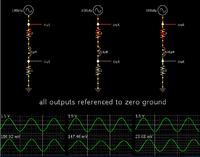
Current through a coil will always lag voltage across it by 90 degrees... provided there is not too great ohmic resistance in the loop.

The inductive time constant (L/R) plays a crucial role here. If your coil has too small a value, or if it sees substantial ohmic resistance, then you will have a tougher time measuring the current lag.

For a sinewave at 100 kHz, you will find there is a certain range of Henry values that work best.

Notice that 1uH produces only slight current lag. As you increase the value you'll see greater current lag.


The 7 ohm resistors represent some amount of ohmic resistance in the coil.

The AC source may also have some internal resistance. This will influence your time constant.
 
Hi all,
Thank you for the suggestions,
@LvW
AD620 I am using at a gain of 5.94~6 by putting a resistor of 10KOhm across. I use the high side current detection mechanism by putting a 1ohm resistor at o/p of current buffer.
In order to reduce input current , I put a 10kohm resistor at "-" input terminal of AD620 and at "+" I put a 10Kohm and another from referance to "+" terminal. I understand that instrumentation amplifiers have input buffers, so I though they would be good to measure the small volatage drop across 1 ohm.

@BradtheRad
Thank you for the waveform and explaination, I am saying about the phase change calculation and the errors that might have crept in the circuit.

Regards
Kshatriya
 

and another from referance to "+" terminal
Why? Sounds definitely wrong.

Generally speaking, you would to test the current sense operation under well defined conditions first. ("calibrate" the sense amplifier)
- no output without a load
- correct output with defined resistive load
- correct output with defined capacitive load
 
Just a difference amplifier configuration and to reduce the offset changes. Also by removing that resistor the output voltage just clamps to a small DC value.


I am also trying to that with a defined load and resistor values.
But even with no load, I get a sinusoidal output at sense amplifier.
Kshatriya
 
Last edited:

Status
Not open for further replies.

Part and Inventory Search

Welcome to EDABoard.com

Sponsor

Back
Top