Continue to Site

Welcome to EDAboard.com

Welcome to our site! EDAboard.com is an international Electronics Discussion Forum focused on EDA software, circuits, schematics, books, theory, papers, asic, pld, 8051, DSP, Network, RF, Analog Design, PCB, Service Manuals... and a whole lot more! To participate you need to register. Registration is free. Click here to register now.

[SOLVED] PFC Inductor Design for 1500W

Status
Not open for further replies.

caturrn

Newbie
Joined
Jun 17, 2021
Messages
4
Helped
0
Reputation
0
Reaction score
0
Trophy points
1
Activity points
50
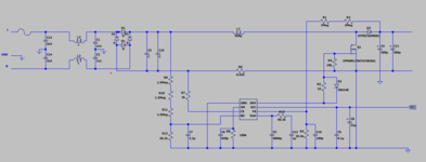
I intend to design an 1500W PFC using ONSEMI's NCP1654 working on 65 kHz, below is the schematic design
The design i intend to is working at EU input with 400V output.
Screenshot 2021-10-07 113845.png


the parts that left for design is the inductor. I trying to design the inductor using example at A-Z SMPS by Maniktala on below

Screenshot 2021-10-07 113808.png


But with the calculation, it result in core size with 103cm^3, When i looked at the ETD datasheet even ETD59 cannot acomplish this core size needs. So i intend to increase the frequency to 200kHz so the size will be dropped. But by doing so, it will result in high switching loss in MOSFET, is it safe to increase the frequency to 200kHz?

and another question, as the example is ETD core, can i convert it into toroid?
thanks
 

Solution
If we look at the peak of the mains, 325V to 400V say, and assume CCM, the on time will be ~ 0.20

We need an L value to give us ~ 3A in the 65kHz period, V/L = di /dt, where V = Vin, di = 3A, dt = 3uS

ergo L = 325uH, and needs to handle 12A pk say

Given that Lmax = Nmax . Ae . Bmax / Ipk

and that for ETD59 Ae = 375mm^2 ( allowing for the gap ), we know L, Ae, Bmax ( 0.28T ) and Ipk ( 12A say )

therefore Lmax = Nmax . 8.75 E-6, for L = 325uH, N must be 37 Turns, => this will easily fit on an ETD59 bobbin with a given current of 8.5A rms

We need to calc the gap, AL ( nH/N^2 ) = Uo.Ur. Ae / Lgap, for the gap ( air ) Ur = 1, we know AL desired from...
is it safe to move the freq to 200kHz ? yes if the boost diode is SiC, no otherwise.

can you convert to toroid ? yes - as long as it is a correct type of material.

1500W / 200Vac = 8 amp rms say, ~ 12A pk, pk-pk ripple = +/- 1.5 amp say, have you designed for this ?

ETD59 should be fine for Bpk = 280mT say, can you show your workings ....?
 

is it safe to move the freq to 200kHz ? yes if the boost diode is SiC, no otherwise.

How about the switching loss that occur on the mosfet?

can you convert to toroid ? yes - as long as it is a correct type of material.

I can't use ferrite for the material can i? as long as i reading about it, it should be air gapped material.

1500W / 200Vac = 8 amp rms say, ~ 12A pk, pk-pk ripple = +/- 1.5 amp say, have you designed for this ?

Yep more or less, unless i design it for 180 Vac input so the rms will be on 8.87 amp rms.

ETD59 should be fine for Bpk = 280mT say, can you show your workings ....?
can you give me any practical theory on magnetic? i only following the guide on the second image so the core selection only be based from effective volume.

anyway, here's my schematic so far: (still working on the inductor, the inductance value is not valid yet)
 

Attachments

  • Screenshot 2021-10-07 135502.png
    Screenshot 2021-10-07 135502.png
    23.1 KB · Views: 204

If we look at the peak of the mains, 325V to 400V say, and assume CCM, the on time will be ~ 0.20

We need an L value to give us ~ 3A in the 65kHz period, V/L = di /dt, where V = Vin, di = 3A, dt = 3uS

ergo L = 325uH, and needs to handle 12A pk say

Given that Lmax = Nmax . Ae . Bmax / Ipk

and that for ETD59 Ae = 375mm^2 ( allowing for the gap ), we know L, Ae, Bmax ( 0.28T ) and Ipk ( 12A say )

therefore Lmax = Nmax . 8.75 E-6, for L = 325uH, N must be 37 Turns, => this will easily fit on an ETD59 bobbin with a given current of 8.5A rms

We need to calc the gap, AL ( nH/N^2 ) = Uo.Ur. Ae / Lgap, for the gap ( air ) Ur = 1, we know AL desired from 325uH/37 turns^2

= 237 nH / N^2, therefore Lgap = 1.98mm in the centre pole or 0.9mm in each leg ( 3 legs ) Uo = 1.256E-6

This is all really basic stuff.
 
Solution
If we look at the peak of the mains, 325V to 400V say, and assume CCM, the on time will be ~ 0.20

We need an L value to give us ~ 3A in the 65kHz period, V/L = di /dt, where V = Vin, di = 3A, dt = 3uS

ergo L = 325uH, and needs to handle 12A pk say

Given that Lmax = Nmax . Ae . Bmax / Ipk

and that for ETD59 Ae = 375mm^2 ( allowing for the gap ), we know L, Ae, Bmax ( 0.28T ) and Ipk ( 12A say )

therefore Lmax = Nmax . 8.75 E-6, for L = 325uH, N must be 37 Turns, => this will easily fit on an ETD59 bobbin with a given current of 8.5A rms

We need to calc the gap, AL ( nH/N^2 ) = Uo.Ur. Ae / Lgap, for the gap ( air ) Ur = 1, we know AL desired from 325uH/37 turns^2

= 237 nH / N^2, therefore Lgap = 1.98mm in the centre pole or 0.9mm in each leg ( 3 legs ) Uo = 1.256E-6

This is all really basic stuff.

Wow thanks

i think i need to look at the textbook again.

anyway, thanks easy peasy!
 

I can't use ferrite for the material can i?
Why you think so ? I'd say for frequencies in Khz ferrite is pretty much your only reasonable choice as in laminated electrical steel above 20 khz has high losses , you would waste lots of power as heat.

The schematic seems like an application generic schematic from the manufacturer , if I might ask , how did you calculate all the component values, did you use a template from a known schematic or did everything yourself? This is a critical part as any values that are off the mark might cause your circuit to malfunction.

Also this PFC seems like based on the boost type topology, just for interest have you studied how they work?
Oh also do you have a scope? A scope really helps in building these high frequency switching circuits especially high power ones. It is much easier to diagnose any problems that way.


Oh one more thing, what is the mains voltage at your place , 230 VAC? do you have a variable autotransformer? I would use a variable autotransformer to first power it up with probes attached to see whether things are working out OK, in this way you lessen the chance that if something is wrong or a mistake is made everything would go up in smoke.
 
Status
Not open for further replies.

Similar threads

Part and Inventory Search

Welcome to EDABoard.com

Sponsor

Back
Top