Continue to Site

Welcome to EDAboard.com

Welcome to our site! EDAboard.com is an international Electronics Discussion Forum focused on EDA software, circuits, schematics, books, theory, papers, asic, pld, 8051, DSP, Network, RF, Analog Design, PCB, Service Manuals... and a whole lot more! To participate you need to register. Registration is free. Click here to register now.

Performance of max485 communication

Status
Not open for further replies.

Murugesh_89

Full Member level 5
Joined
Nov 23, 2012
Messages
266
Helped
7
Reputation
12
Reaction score
6
Trophy points
1,298
Location
India
Activity points
3,267
Hi,
I have attached two configurations for max 485 communication..
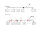
Max485.JPG

Out of these two, Which gives the better performance in communication?

In the configuration 2, i heard that the pcb board in between the max 485 stations acts as router which increase the performance and reduce the data loss. Is it true???


Thanks,
Murugesh
 

The quality of connection between them determines the maximum length, speed and reliability, not whether it's wire of PCB track. There s certainly no 'router' in either configuaration.

Normally the two wires are twisted together to minimize common mode losses and pick-up. You can run them as parallel tracks on a PCB but you will have less immunity from interference and ideally you should ensure the tracks maintain constant imedance throughout their whole length. I would say that depending on distances and cable quality, the first schematic would work best. RS485 is a robust system though so I'm not saying the second diagram will not work.

Brian.
 
Thanks brian.

Also one more question...
If the distance between the two end stations is 200 meters and
a. There are 30 stations between the end stations
b. There are 10 stations between the end stations

Of these a and b, where the performance is good.

I mean, how the number of intermediate nodes have the effects in performance?

Thanks,
Murugesh
 

Each MAX485 draws a little current from the wires and adds a small capacitance to it so the more you add the poorer the signal quality will become. They should reach full specification with up to 32 end stations and in reality you can usually add even more before they stop working but that isn't guaranteed.

Brian.
 
Ok fine..
When i programmed like this..
Code:
#define MAX485_TXDIS_RXEN RC5 = 0;
#define MAX485_TXEN_RXDIS RC5 = 1;
void main()
{
	cpu_initialisation(); 
    
   	while(1)
   	{
		if(comm_over == 1) // set in receive interrupt when a byte receives
		{
			comm_over = 0;
			MAX485_TXEN_RXDIS
			[B]delay_ms(15);[/B]
	                putc(received_data);
			delay_ms(2);
			MASTER_MAX485_TXDIS_RXEN 
			[B]delay_ms(15);[/B]
		}		
   	}
}

If i failed to put the delay_ms(15) in bold, it is not working.. even if i put the delay as delay_ms(5) this is not working. why should i give 15 milli seconds delay after changing the mode(tx/rx).

thanks,
murugesh
 

I'm not sure but I don't think it has anything to do with the RS485 itself. I suspect the problem is you are overwriting the UART before it has time to send the previous character. Perhaps adding the delay is giving it time to empty it's transmitter before reloading it again. Does the putc() function in your compiler check to see if the transmitter is free before sending data to it? You also have to check the UART has sent the last bit before disabling the RS485 transmit and returning it to receive mode.


Brian.
 
1. Normally we will terminate the last max485 node using 120 ohms resistor( characteristic impedance of wire ). Suppose if some one uses a ideal wire with the characteristic impedance as zero, then is there anything to be done with the termination?

2. In max485 communication, when a station wants to transmit it will change to transmission mode and after transmission again it will switch back to reception mode. The transmitting station is normally selected using a address set in the station. Suppose unknowingly if two stations have been set to same address, then both the stations try to transmit simultaneously results in improper data received at the master station. Is there anyway to overcome this issue?

Thanks,
Murugesh
 

1. that's a hypothetical situation as nobody ever will! The drivers are optimized for driving twisted pairs anyway so an 'ideal' transmission line probably wouldn't work any better.

2. Obviously you try not to get into that situation but it can happen. The only way around it to reset one of the addresses because no matter how many times you try, the two stations will always clash with each other. There is one danger to be aware of though, suppose the stations are all listening but no master is driving. The lines will 'float' to indeterminate states and it's possible that random data would come out of the receivers. In that situation, it is possible for the random data to be interpreted as an address and falsely trigger some event. The cure I use is to tie one line low with a 1.8K resistor and the other line high with a 1.8K resistor. With a 120 Ohm terminator effectively beween them, even though it may be at the other end of the cable, it will ensure that undriven lines go to a predictable and safe state.

Brian.
 
For max485 communication i saw various values of pull up and pull down resistors for A and B respectively while searching. The values are 560E,2.2K,4.7K and you preferred 1.8K. How to determine this value?

Also i am using MAX487 IC to communicate across 84 slave nodes. For this IC what value of pull up and pull down to be used for A and B?

I am using the pull up and pull down resistors only in master station and all the slaves are pull up and pull down free. Where the 120E termination resistors to be placed?
1. In both the master and last slave unit
2. Master unit only
3. Last slave unit only


Thanks in advance.
 

The pull-up/ pull-down resistors are there to ensure the lines adopt a known logic level when NOT being driven, otherwise with all the drivers disabled, they would float and could be seen as high, low or just as noise.
The terminator goes at the most distant part from the transmitter so to work in worst case situations you should have one across both wires an physically located at the two most distant points in the network.

The terminator values should match the cable impedance which for normal UTP (CAT-5 style) is around 120 Ohms. The pull up/down resistors should have values chosen so that the idle voltage across the wires is > 0.2V. In other words "ground -- R1 -- 120 -- R2 -- VCC" should drop at least 0.2V across the 120 in the middle. So if you have two outgoing wires and two incoming wires (RS422) they would each have a single 120 Ohm resistor across them and the resistors should be no higher than 1.8K giving approximately 2.4V and 2.6V on the wires. In an RS485 configuration there will be two 120 Ohm resistors in parallel although they may be located some distance apart so twice the 'pull' current is needed and the highest values will therefore be 900 Ohms.

You can use lower values but you waste more current if you do. Please remember that in many instances you may not even need a terminator and then much higher values can be used or the resistors may not need to be fitted at all. It all depends on the speed of your data and the quality of the wiring, the values I show are the minimum to ensure it will work under worst case conditions.

Brian.
 
Hi i have faced an issue recently. I am using a 4 pin connector carrying 12V, Gnd, Rs485 A, Rs485 B.
Accidentally the 12V line in the connector shorted with Rs485 A line. Then all the max487 IC's get damaged.
By the way i have a single master with 10 slave station. Hence 11 max487 IC's got fired.

Is there any protection circuits available to prevent the above issue?

Thanks,
Murugesh
 

The only protection I can think of is to add a fuse in the 12V line. Under normal operation the current drawn by each IC is quite small so there should be a big difference between normal and fault operation.

Brian.
 

What happen if we put a separate TVS diodes for A and B lines to ground. Will it work?
 

TVS will not help, they protect against excessive voltage but in your case it is the current that is too high. What has happened is you have connected 12V directly to a line which is only suposed to handle a maximum of 5V and with a small current. As the RS485 lines go low in normal operation, the current is fed to ground anyway. You could try connecting ordinary signal diodes from both signal wires, one diode to ground and the other to 5V, wired so they are normally not conducting. That would divert any excess current into the supply lines where it is easier to 'lose'. A big fat Zener diode, rated at 5.1V across +5V and ground would absorb enough current to protect the driver ICs.

Brian.
 
i want to try what you told. before that i just want to ensure whether i understand correctly.

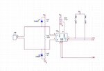
MAX485 issue.jpg

My doubts are..
1. Does the circuit connection of diodes in the above circuit is correct?
2. Should i add the diodes for both master and all the slave circuits or Is it enough to connect only to master


Note: The above mentioned circuit is master whereas the slave does not have R37,R38,R39
 

1. Almost correct - add another two diodes, one in series with each of the present ones and connected to the other supply/ground. At the moment you have one wired correctly in each of the A and -B wires, you need the same in the other wire. It should look like you have two diodes in series on each wire, one to ground and one to +5V, the actual data voltage is too low to make them conduct so they will have negligible effect but if the voltage exceeds 5V or goes below zero volts, one or the other diode will conduct and drain the excess current away.

2. You only need them once in the circuit but you can add them to slaves as well if you want. RS485 allows for small variations in ground voltage between nodes so if you do not have a good ground connection, it would be wise to add them to a slave as well so the most appropriate route for the excess current is used. Something to beware of: IN400x diodes have quite a high capacitance across their junctions and this will slightly load the signal on the lines. The effect will be small and you probably wont notice it but if you use high speed data (>250Kb/s) and long cables it would be worth looking at lower capacitance diodes, possibly schottky types.

You are right to use the resistors only once in the circuit, they are there to ensure that idle (undriven) lines adopt a known logic level and do not produce random signals.

Brian.
 
Status
Not open for further replies.

Similar threads

Part and Inventory Search

Welcome to EDABoard.com

Sponsor

Back
Top