Kick
Full Member level 6
- Joined
- Sep 27, 2010
- Messages
- 344
- Helped
- 16
- Reputation
- 32
- Reaction score
- 15
- Trophy points
- 1,298
- Location
- India,Bangalore
- Activity points
- 3,170
Follow along with the video below to see how to install our site as a web app on your home screen.
Note: This feature may not be available in some browsers.
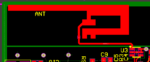
![CropperCapture[14].png](/data/attachments/46/46030-e0fb466fd00fff009fd4e7af95d22f6c.jpg)