Continue to Site

Welcome to EDAboard.com

Welcome to our site! EDAboard.com is an international Electronics Discussion Forum focused on EDA software, circuits, schematics, books, theory, papers, asic, pld, 8051, DSP, Network, RF, Analog Design, PCB, Service Manuals... and a whole lot more! To participate you need to register. Registration is free. Click here to register now.

PCB Layout for Burnt CFL re-light

Status
Not open for further replies.

gameshark888

Newbie level 3
Joined
Nov 11, 2010
Messages
4
Helped
0
Reputation
0
Reaction score
0
Trophy points
1,281
Activity points
1,312
Has anyone tried building this schematic found at https://makelifeeasy.yolasite.com/

this is the circuit
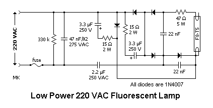
linefl.gif


and i wanna make a PCB Layout of the circuit.. any one wanna help me out.. i wanna try this with some of my burnt CFL bulbs.. thnx in advance.. =]
 

Please note that the schematic is not intended for CFL but for full-size cold-cathode fluorescent lamps.
In particular note that it does not drive the heater elements and the size of the resistors. I would not advise building it into a small CFL lamp base !

Brian.
 

the schematic is not intended for CFL but for full-size cold-cathode fluorescent lamps
The link is suggesting the circuit just for the former.
 

If you re-draw the schematic it is simply a bridge rectifier across the 220V with a capacitor as current limiter. The electrolytic caps are across the DC output and the tube is fed via 47 Ohms and another diode. In other words it works on DC and has no start-up circuit. I would be worried the tube might explode and release mercury vapor. It would probably work equally well (or badly) with just the series capacitor and tube in series across the AC and all the other components omitted. With the values shown, at 50Hz and assuming no harmonics or spikes, the tube could be dissipating over 30W.

Brian.
 

Many have markted this simple circuit in India and minted money once upon a time when our state was facing acute low voltage problems. The advantage boasted about was it can run blackened and those tubes whose fillment was open and was able to glow a 40 watt tube with just 100 volts, and another advantage was with little components which were sealed in a small plastic container with a hardening sealent so that the cicruit was not traceable. In surprise i had bought one and carefully opened annd for my surprise, i found 4 IN4007 diodes forming a bridge and two 2.2Mfd/400V polyester capacitors which were connected across the diodes which were giving out the negetive DC out. To be on the safer side, the installtion diagram had suggested to connect the AC to the circuit in series with the existing regular choke with windings or a 100 watt bulb. But later every one realised that it was mandatory to use only old and useless tube with this circuit. Using a new tube will blacken the ends within a week or so.
But the present given circuit is some what different when current controlled by resistors. I personally dont recomend it for a CFL or any other application. Use a electronic ballast design instead. All details are freely available on the IR website.
http://www.irf.com/technical-info/appnotes/an-1056.pdf
http://www.irf.com/technical-info/appnotes/an-1074.pdf
Cheers
 

Has anyone tried building this schematic found at https://makelifeeasy.yolasite.com/

this is the circuit
linefl.gif


and i wanna make a PCB Layout of the circuit.. any one wanna help me out.. i wanna try this with some of my burnt CFL bulbs.. thnx in advance.. =]

please indicate the voltage/ watts of 2x 22nf caps and 330k Resistor.
 

I found 3w cfl in market. Bought a cartoon to put as nigh lamp, in stairs and here and there replacing high power CFLs to conserve energy.Within a week it was found that most of them turned black at their ends with diminished light. Some of them even failed to lit. I opened them and found similar type of circuit inside instead of hi-frequency switching circuit normally used in CFLs. I suspect the circuit to fail the CFL due to inherant short high voltage and current spikes during charging capacitors in circuit.
 

Status
Not open for further replies.

Similar threads

Part and Inventory Search

Welcome to EDABoard.com

Sponsor

Back
Top