hummusdude
Newbie
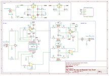
This is my first board so I'm sure it has some issues. It's an audio pre-amp with active 2-band tone. I made this to go with a power amp design I found online. I intend to put it in the case with the power amp. The power supply for the power amp is beefy and puts out +- 25VDC so I'm using that to supply this pre-amp board. For fun I added some different controls to trigger the microcontroller. The Nano is used just to control the dpot that controls the gain of the pre-amp, and to drive the shift registers that control the two 7-segment displays.
Some questions I have...
Is the 5VDC linear regulator too close to the analog section?
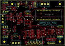
I tried to keep all of the signal lines on top but there a couple of places where I had to use the bottom. I kept them as short as possible and at right angles. Is that okay?
Does it make a difference in the overall power dissipation if I supply the 5V linear regulator from 15VDC or 25VDC? I understand the power loss issue but not sure if it matters in this case.
The treble/bass controls are potentiometers that I will panel mount on the front of the case. Is it okay to twist all three wires for the run from the front panel to the board connections to help with emi?
Some questions I have...
Is the 5VDC linear regulator too close to the analog section?
I tried to keep all of the signal lines on top but there a couple of places where I had to use the bottom. I kept them as short as possible and at right angles. Is that okay?
Does it make a difference in the overall power dissipation if I supply the 5V linear regulator from 15VDC or 25VDC? I understand the power loss issue but not sure if it matters in this case.
The treble/bass controls are potentiometers that I will panel mount on the front of the case. Is it okay to twist all three wires for the run from the front panel to the board connections to help with emi?