Alper özel
Member level 1
- Joined
- Feb 28, 2015
- Messages
- 40
- Helped
- 0
- Reputation
- 0
- Reaction score
- 0
- Trophy points
- 6
- Location
- Turkey / Scotland
- Activity points
- 487
Hello,
I (am supposed to) design mainboards for TV units. In our mainboard we need to add a parametric voltage stabilizer before panel supply.
Here is the situation. Our power supply may be varying between 11.8V and 14.2V and our Panel accepts maximum 13.2V (Absolute maximum). So, the ideal function we need is something like this:

The output PANEL_PWR must follow the input while input is below threshold 13.2V but if input exceeds 13.2V it should regulate it.
To do that I added this circuit:

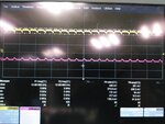
The circuit in the red line is fixed standart power shutdown circuit of us and I can not make any changes on that. So I added the parametric stabilizer circuit in green line. The problem with this stabilizer is that it manages to trigger when the threshold is exceeded but it has enormous ripples:

between 10KHz to 23KHz, up to 4V ripple when input voltage hits to 14V and above.
So can you suggest me anything here? Ripple must be below 300 Vpp and threshold must be below 13.2V. At this point I have to warn you that we do not use opamps! This circuit can be formed by only transistors, references etc. simple components.
Thanks per advance.
I (am supposed to) design mainboards for TV units. In our mainboard we need to add a parametric voltage stabilizer before panel supply.
Here is the situation. Our power supply may be varying between 11.8V and 14.2V and our Panel accepts maximum 13.2V (Absolute maximum). So, the ideal function we need is something like this:
The output PANEL_PWR must follow the input while input is below threshold 13.2V but if input exceeds 13.2V it should regulate it.
To do that I added this circuit:

The circuit in the red line is fixed standart power shutdown circuit of us and I can not make any changes on that. So I added the parametric stabilizer circuit in green line. The problem with this stabilizer is that it manages to trigger when the threshold is exceeded but it has enormous ripples:

between 10KHz to 23KHz, up to 4V ripple when input voltage hits to 14V and above.
So can you suggest me anything here? Ripple must be below 300 Vpp and threshold must be below 13.2V. At this point I have to warn you that we do not use opamps! This circuit can be formed by only transistors, references etc. simple components.
Thanks per advance.