Continue to Site

Welcome to EDAboard.com

Welcome to our site! EDAboard.com is an international Electronics Discussion Forum focused on EDA software, circuits, schematics, books, theory, papers, asic, pld, 8051, DSP, Network, RF, Analog Design, PCB, Service Manuals... and a whole lot more! To participate you need to register. Registration is free. Click here to register now.

Paralleling of Mosfets

Status
Not open for further replies.

doubled312

Newbie level 3
Newbie level 3
Joined
Apr 21, 2013
Messages
3
Helped
0
Reputation
0
Reaction score
0
Trophy points
1,281
Visit site
Activity points
1,306
I'm working on a project that requires paralleling of 2 mosfets. I attached the wiring diagram for just the two mosfets below. Basically the gate on each mosfet is connected to their respective pin on a PIC microcontroller. When the respective pin is high, the respective MOSFET is turned on and sends a current through the coil. The transistor at the bottom has a resistor connected to the drain to reduce current flow to the coil when that transistor is on.
The PIC is programmed such that the two pins on the PIC can't be high at the same time. Only one can be high at a time. Basically, we want to send two different currents/voltage drops through/across the coil depending on whichever pin is high.

Do you guys see any problems with this wiring diagram?
thanks.
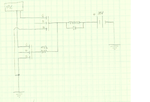
Untitled.png

- - - Updated - - -

Another note: when I tested the circuit with one MOSFET it behaved as expected. When I added the second MOSFET in parallel, both MOSFETs turned on at the same time when either was activated.
 

Attachments

  • Document.pdf
    369.1 KB · Views: 96

Your MOSFET symbols are incorrect, you confused drain and gate terminal.

The circuit according to your text description should work nevertheless. How do you know that "both MOSFETs (are) turned on at the same time when either was activated"?
 

Your MOSFET symbols are incorrect, you confused drain and gate terminal.

The circuit according to your text description should work nevertheless. How do you know that "both MOSFETs (are) turned on at the same time when either was activated"?

Are you saying that we should wire everything on the gate (as shown "currently") to the drain instead and vise versa (everything shown on the drain currently to the gate)?


I say that the symbols are wrong. You have drawn a G letter where a D letter should be. Refer to any MOSFET datsheet or electronic textbook to learn about the correct symbol usage. https://en.wikipedia.org/wiki/File:IGFET_N-Ch_Enh_Labelled.svg

https://en.wikipedia.org/wiki/MOSFET

I am pretty positive I have it wired up right. The problem is that for some reason both transistors turn on when only one of them is supposed to be on. Instead of using the 10 ohm resistor, I used a 100kohm resistor and it worked like it was supposed to, but the resistance is too large for my purpose. I don't understand why having a smaller resistor would turn both of them on.
 

You still didn't tell how you exactly determined that both MOSFETs are turned on. Reporting Vgs and Vds measurements would be a way to clarify the point.

For the time being, I'll assume a misunderstanding of circuit operation.
 

Status
Not open for further replies.

Similar threads

Part and Inventory Search

Welcome to EDABoard.com

Sponsor

Back
Top