Johansen
Member level 4

- Joined
- Feb 10, 2008
- Messages
- 76
- Helped
- 13
- Reputation
- 26
- Reaction score
- 10
- Trophy points
- 1,288
- Activity points
- 1,844
I want to make a transition mode PFC for perhaps tens of kilowatts, running off 120 or 240vac, output 360-400Volts as standard.
to keep components resonable given the availability of power, at 120vac the supply only needs to deliver half the power at 240 vac.
so the power limits are more of a current limit rather than a power limit, lets make it 30 amps.
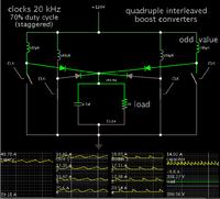
normally this would be done with a dual interleaved CCM boost but i'd rather have more phases and use a transition mode high frequency design, primarly because i have a lot of ferrite E cores available.
So i was thinking, i can take the L6562 or equivalent transition mode boost converter and drive multiple slave components by simply wiring the error amplifier for a gain of -1 and feeding it from a master error amp (i would use a discrete opamp on a separate card, to have more control over the system as well as providing redundancy, and making the total output power of the system modular)
my question is, due to the ESR and ESL of the single low value capacitor fed from the single phase ac grid, i could see in my mind all of these Transition mode converters would end up lumping together and running at one frequency.
one way to force them all to run at a different frequency i suppose would be to make the inductor values all differ by at least 1%
so i've been trying to come up with creative ways to force the converters to oppose each other.. and i can't think of any. due to the duty cycle ranging from 10% to 95%, there's no good way to hook up passive components to force them all to run anti-phase.
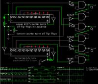
one idea i came up with was to make a ring oscillator from inverting schmitt triggers and wire the output to OR gates, and then hook that into the inductor current sense, so the TM mode converter would not switch on until the master oscillator allowed it too..
but that doesn't work because the duty cycle needs to be as high as 99%, not to mention the frequency is changing as well.
so i'm thinking its probably acceptable to just eat the beat frequencies and just let them all run at their own freq, the reduction in input and output current ripple from just three of them free running in parallel is more than adaquate.. with upwards of 10 of them running in parallel i think effectively there would be zero current ripple on the line. --unless they all end up running at the same frequency.
any thoughts?
--the current is naturally shared according to the tolerance of the onboard multiplier. since each chip will get the exact same voltage fed from the error amp (by nature of the -1 gain each would be wired for, and the same voltage to the ac voltage sense pin (since they would all run in parallel)
then the output of the multiplier should be within 10%.
each boost mosfet or igbt would have its own current sense resistor, so if you really wanted to get them all to share the current equally you could hook up a potentiometer to scale each individual error amp gain +/-10%


